Microphone Input
A high-performance microphone preamplifier circuit provides low-noise/low-distortion amplification over a 20 to 60 dB gain range. The gain is adjustable in 10 dB steps. The input is compatible with balanced dynamic or condenser microphones. The microphone power source is 48 V nominal and meets the worldwide P48 phantom power standard. The preamplifier's gain can also be set for 0 dB, allowing a line-level audio signal to be connected. This could prove useful in special applications such as when an external preamp or mic processor is being used.
An LED indicator serves as an aid for optimizing the setting of the preamplifier's gain. The output of the microphone preamplifier is used by the main output as well as being routed to the compressor circuit that supports the talkback function.
Main and Talkback Outputs
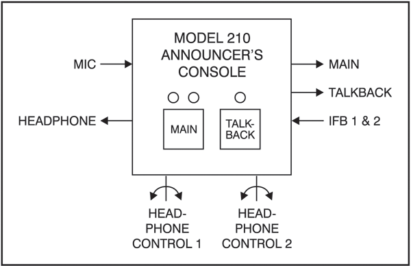
The Model 210 provides one main and one talkback output. The main output is designed to serve as the on-air, stadium announcement, or other primary audio feed. With a nominal level of –2 dBu, it is designed as a fully professional interface with high output capability, low distortion, and low noise. It features a high-quality transformer expressly designed for driving long broad- cast cable runs. The talkback output is intended to provide production trucks, control rooms, or support personnel with a talent-originated cue signal. The talkback output is transformer-coupled with a +4 dBu nominal signal level. It contains resistors in series with its output connections, allowing the talkback output from multiple units to be directly summed (combined).
For non-on-air applications, a special Model 210 feature can be enabled, placing the unit in a "production" mode. This allows the main output to be used as a second talkback output. In this configuration the unit can be even more powerful when used in a live event application, such as serving as a master console for a production director.
Dynamic Range Control
A studio-quality compressor circuit is provided to control the dynamic range of the signal coming from the microphone preamplifier. Far from a simple "clipper," the circuit utilizes a sophisticated laser-trimmed voltage-controlled-amplifier (VCA) integrated circuit for quiet, low-distortion level control. The signal from the compressor is always used by the talkback output. In addition, the audio source for the main output can be selected to be either the output of the microphone preamplifier or the output of the compressor.
User Controls and Status Indicators
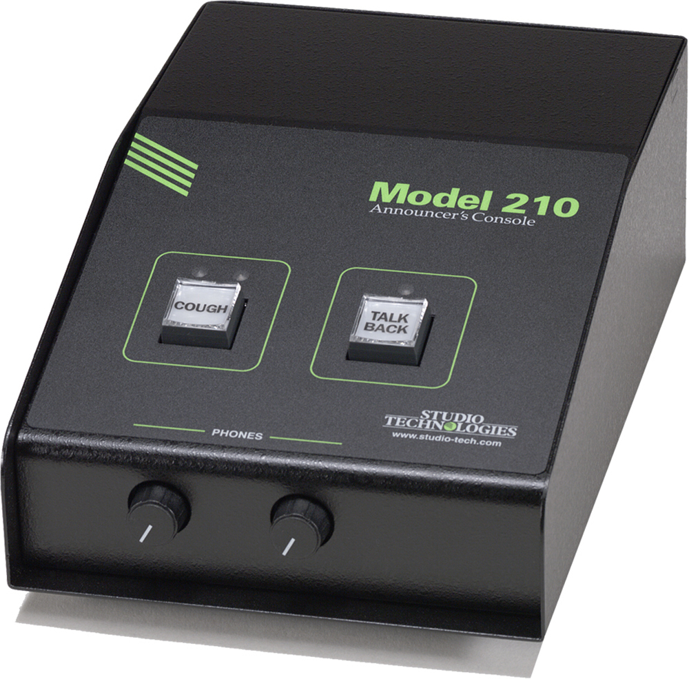
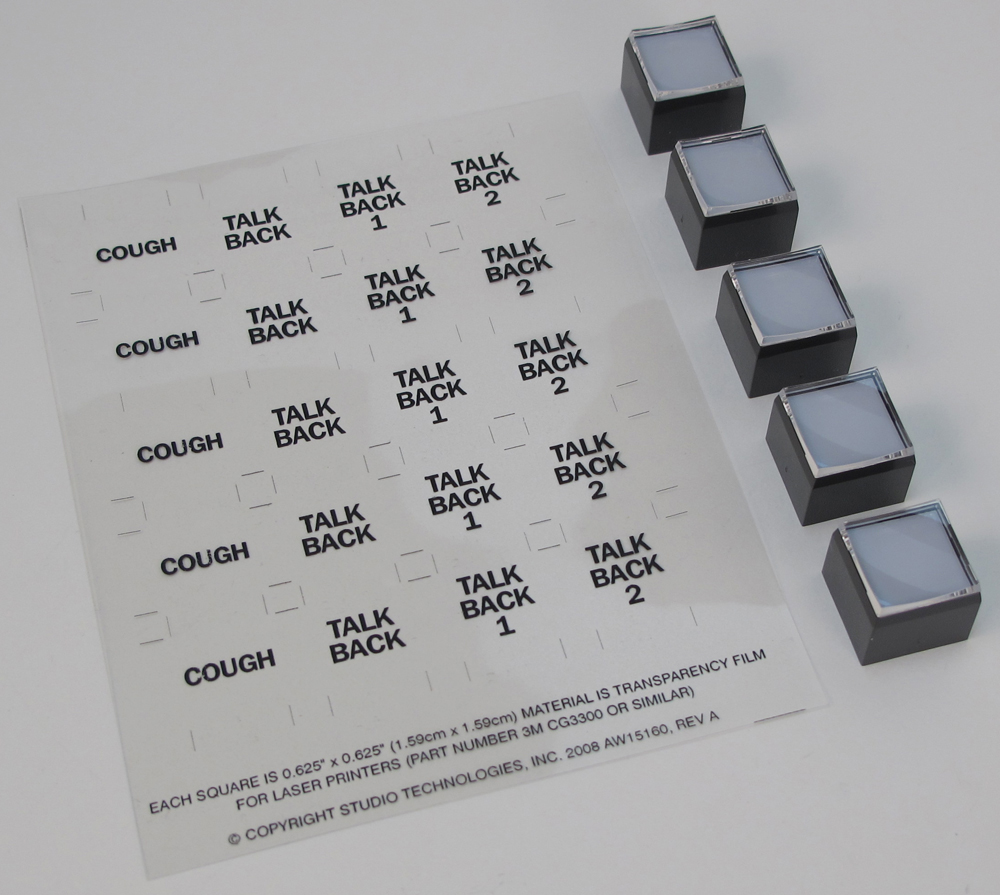
Two pushbutton switches, three LED indicators, and two rotary controls provide the user with a clear, easy-to-use interface. One pushbutton switch controls the status of the main output. This is the audio output intended for on-air, announcement, or other primary uses. Two LEDs display the on/off status of the main output. A second pushbutton switch controls the status of the talkback output. This is the audio output used to communicate with producers, directors, spotters, or other behind-the-scenes production personnel. A status LED is associated with the talkback button. Two rotary controls allow the user to adjust the level of the headphone output.
Flexibility
A large part of the Model 210's unique power is the ability to configure the operation of the main output and talkback functions. To meet the needs of the many specific broadcast and production applications, a variety of button operating modes is available. The main output button can be selected to operate from among four modes. In the "push-to-mute" mode the button performs a momentary mute of the main output. In this way a "cough" button function is created, something typically required for television sports broadcasting. In the "push-to-talk" mode the button provides a momentary active function for the main output. This mode would be appropriate for applications such as stadium announcement. An alternate action "latching" configuration allows the button to enable or disable the main output as desired. This is useful in radio broadcasting, announce-booth, or voice-over applications. The fourth mode provides a hybrid function, supporting both push-to-talk and tap-to-enable/tap-to-disable operation. This operation is similar to that found in many broadcast intercom system user stations.
The button associated with the talkback function can be configured to operate from either of two modes. One of the modes supports a "push-to-talk" function. This is typically used for on-air broadcast applications. The other mode provides a hybrid function, the operation of which is discussed in the previous paragraph. The hybrid mode is especially useful when the Model 210 is used in a production-support application.
IFB Input
A broadcast-standard "wet" (DC with audio) IFB circuit can be directly connected to the Model 210's IFB input. Originated by sources such as the RTS® 4000-series IFB system or IFB interface devices from Studio Technologies, the connected IFB circuit can provide the DC power to operate the Model 210 as well as two channels of cue audio.
Cue Sources
The Model 210 allows the two audio sources associated with the IFB input to be selected for routing to the headphone output. Originating in production trailers, control rooms, or remote locations, these unbalanced sources normally provide DC power and program-with-interrupt audio on one channel and program-only audio on the other. Each source can be individually assigned to the left channel, right channel, or both left and right. This allows a wide variety of stereo and mono headphone mixes to be created.
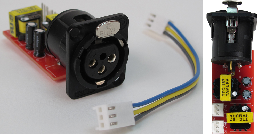
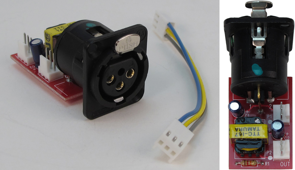
Some applications may benefit by being able to connect standard line-level audio signals to the Model 210. To meet this need one or two optional line input cards can be installed in the Model 210's back panel. Each card provides a 3-pin female XLR connector and transformer-isolated +4 dBu nominal input circuit. Each source can be individually assigned to the left channel, right channel, or both left and right.
Headphone Output
Two rotary controls are provided for user adjustment of the headphone output levels. For application flexibility the actual function of the two "pots" is configurable. For traditional on-air sports applications they can be selected to the dual-channel ("level/level") mode which provides independent control of the left- and right-channel volume. For use with dual-channel cue signals, or to support user preference, the stereo ("level/balance") mode can be selected. In this mode one control adjusts the overall level of both the left and right channels, while the other allows adjustment of the left/right level balance. To help minimize the chance of broadcast cues being missed, both level control modes can be configured so that a minimum headphone output level is maintained. Alternately, the headphone output can be set to fully mute when the controls are at their minimum position.
Provision has been made to support applications where a monaural cue feed is desired. A configuration switch allows the summing (combining) of the selected left and right headphone sources. In addition to creating a dual-channel mono output it also allows the level controls to be configured as a simple 2-channel mixer.
The headphone output was designed to meet the needs of contemporary headphones and headsets. Specifically, the output circuits act as voltage, rather than power, drivers. In this configuration they can provide high output levels with very low distortion and noise, along with minimal current consumption. The output circuits are configured to safely drive stereo or mono loads. This ensures that all types of headphones, headsets, and earpieces can be directly connected.
Audio Quality and Protection
The Model 210's circuitry is carefully tailored to provide excellent audio performance. Professional-quality components are featured throughout. For reliability all audio routing is performed using solid-state devices. In all critical audio paths, "clickless" electronic switches provide noise-free control. All audio inputs and outputs make extensive use of protection components. This limits the chance of damage from ESD and other undesirable, yet real-world, hazards.
Power Sources
The Model 210 can derive its operating power from either the IFB input or an external nominal 24 Vdc source. For redundancy, both power sources can be connected simultaneously. An internal switch-mode power supply ensures that all Model 210 features are available when the unit is powered by either source.
The Model 210 is compatible with IFB circuits provided by most standard broadcast systems. However, maximum performance can often be obtained by using the IFB interface devices available from Studio Technologies. Single-channel and four-channel units are available, each providing high-quality audio along with an excellent source of DC power. They're directly compatible with most matrix intercom systems, as well as standard line-level audio signals.
Relay Contact
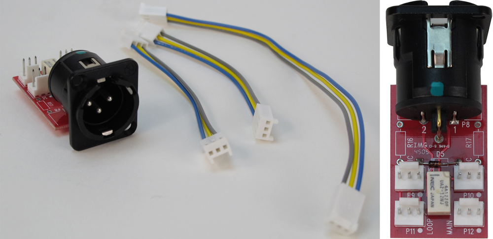
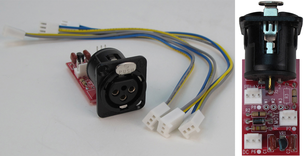
The Model 210's circuitry includes a general-purpose relay contact allowing specialized configurations to be created. Under software control, the form-A (normally open) solid-state relay contact can be configured to follow the state of either the main or talkback output functions. Taking advantage of the locations provided for additional XLR connectors, a technician may easily implement a variety of functions such as mic active indication, audio muting during talkback, or audio insertion control.
Configuration
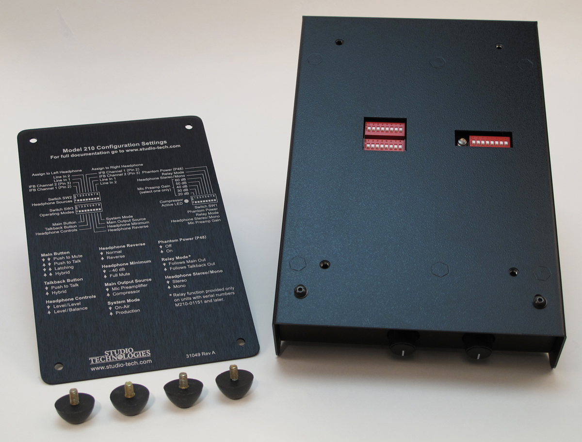
Model 210 configurations are made using a number of DIP-type switches. One 8-position switch array is used to set the gain of the microphone preamplifier, the on/off status of phantom power, and the headphone stereo/mono mode. Another 8-position switch array configures which of the IFB and auxiliary audio sources are routed to the headphone output. A third 8-position switch array communicates the desired operating modes to the microprocessor. All switches are accessible via the bottom of the Model 210's enclosure; the unit does not have to be disassembled. Changes made to any of the configuration parameters become active immediately. To prevent unwanted access to the configuration switches a security plate, included with each unit, is attached to the bottom of the enclosure.
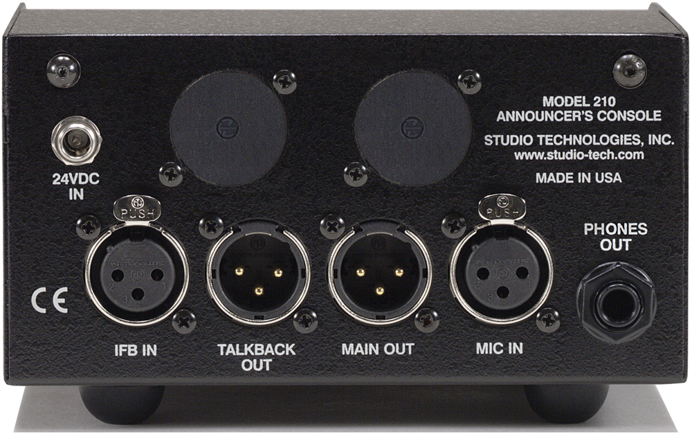
Connectors
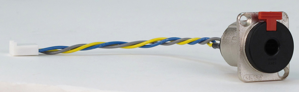
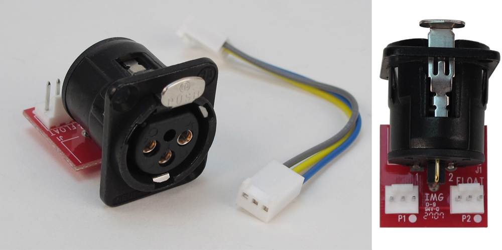
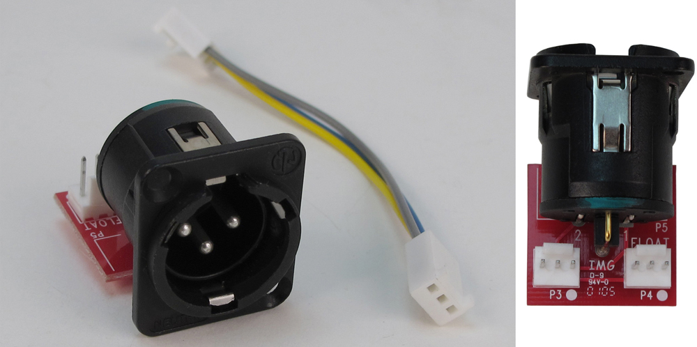
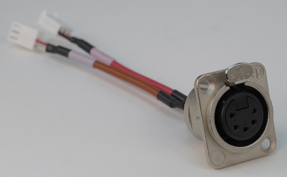
The Model 210 uses standard connectors throughout. The microphone and IFB inputs use 3-pin female XLR connectors. The main and talkback outputs use 3-pin male XLRs. A ¼-inch 3-conductor jack is used for the headphone output. The external source of 24 Vdc power is connected by way of a 2.1 x 5.5 mm "locking" coaxial power jack.
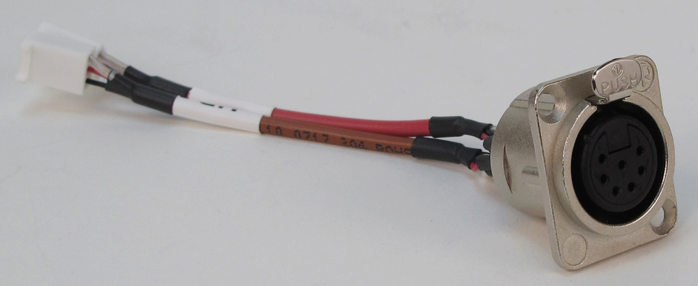
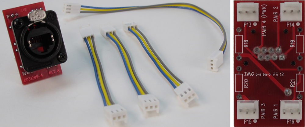
In the world of broadcast and production audio it's fair to say that applications vary widely. To this end, one or two additional XLR connectors can easily be mounted into the Model 210's back panel. Multiple 3-position "headers" located on the Model 210's circuit board provide technician access to all input and output connections. Using a factory-available interface cable kit allows a Model 210 to be optimized to meet the exact needs of specific applications. For example, some applications may prefer to use a multi-pin XLR connector to interface with a headset. This can easily be accomplished by adding the appropriate 5-, 6-, or 7-pin XLR connector and making a few simple connections. Other applications may benefit from having "mult" or "loop-through" connections, something easily incorporated into a Model 210. One or two optional line input cards, as previously discussed, can also be mounted in the spare XLR connector positions.