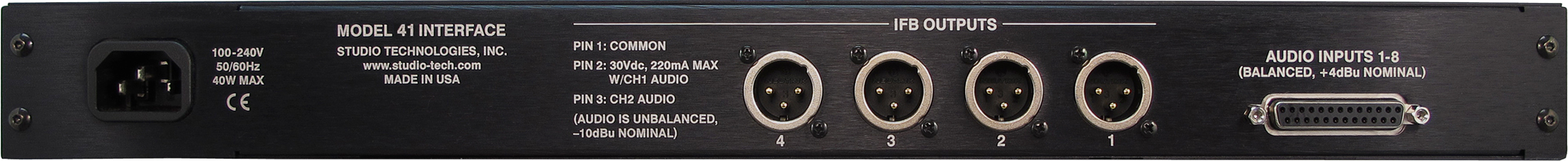
Installation of the Model 41 is very simple. Audio input connections are made using a 25-pin D-subminiature connector. The IFB output circuits interface using standard 3-pin XLR connectors. The compact, one-rack-space package is constructed using rugged steel and aluminum components. The unit's AC mains power input can range from 100 to 240 V, 50/60 hertz. This "universal input" ensures correct operation virtually anywhere in the world.
There may be persons not familiar with the term IFB. That's not unreasonable as it's a somewhat obscure acronym for interruptible foldback. On its own, the term foldback is an alternate way of describing a cue or monitor function. Adding "interruptible" before it means that the cue source can be temporarily replaced with an audio signal originating from a producer, director, or other production personnel. IFB outputs are often used in the broadcast industry for talent cueing applications, both in studio and field settings.
Both "dry" and "wet" IFB outputs can be deployed and their characteristics are worth reviewing. The term "dry" IFB typically refers to a transformer-balanced line-level audio circuit with a nominal level in the range of 0 to +8 dBu. This is essentially a standard analog audio circuit that is commonly used to interconnect audio equipment. The term "wet" IFB refers to a circuit that combines DC power and one or two channels of analog audio. The DC power source is typically in the range of 30 to 32 V. The audio is unbalanced with a typical nominal level of –10 dBu. The Model 41 implements "wet" IFB outputs. As such, in this user guide the term IFB will always indicate this type of circuit.
IFB outputs provide an effective means of delivering power and two channels of audio to user devices by means of standard audio cables. These cables, ubiquitous to the audio industry, interface using 3-pin male and female XLR connectors. Using IFB outputs and standard audio cables it's a simple matter to support user devices such as listen-only beltpacks and announcer's consoles with no external power source required. Whether the IFB source and user devices are 100 or 1000 feet apart, reliable operation can almost always be provided.
In many cases, the Model 41 Interface will be used in on-air television applications. Whether installed in a fixed location or as part of a mobile facility, the unit is capable of providing excellent performance. In addition, the Model 41 can be used for non-broadcast applications. For example, audio recording and post-production facilities can also effectively use the Model 41. Combined with stereo or mono listen-only beltpacks, also available from Studio Technologies, a variety of headphone cue systems can easily be deployed. And since the Model 41's audio inputs are compatible with standard line-level audio signals virtually any analog source can be connected.
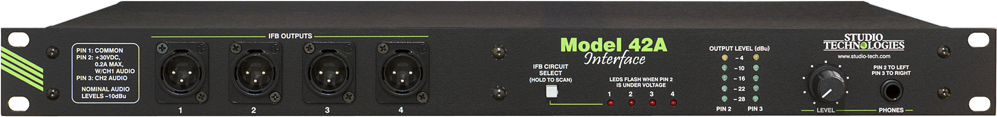
Four Independent IFB Outputs
The Model 41 supplies four independent IFB outputs. Each circuit consists of two audio inputs and a 2-channel "wet" IFB output. The audio inputs are transformer coupled, have a nominal level of +4 dBu, and are compatible with balanced or unbalanced sources. In on-air television broadcast applications the audio sources will often be analog outputs from matrix intercom systems. Two sources are typically designated to serve as a 2-channel user cue signal. Generally one source is configured in the matrix intercom system as "interrupt" while the other is configured as "program." An alternate term often used for the "interrupt" channel is "program-with-interrupt." This may be more descriptive as the function is actually a program source that gets interrupted with talkback audio. The "program" channel is typically a continuous source of program audio. An alternate term is "program-only."
For other applications, the Model 41's audio inputs can be connected to a 2-channel or stereo audio source. This configuration may prove useful in radio broadcasting, audio-with-picture, or recording studio applications. The specific application will dictate whether both cue signals will be utilized by the end user. In on-air sports broadcast situations a "double-muff" (stereo) headset will provide a user with both audio channels, one for each ear. In interview or news-gathering applications it's common to use a single "earpiece" to provide a user with only program-with-interrupt audio.
Maintaining excellent audio performance was a major Model 41 design goal—the hiss, hum, and noise associated with typical IFB outputs was simply not acceptable. The Model 41 meets those requirements with audio that is "on-air" quality: low distortion, high signal-to-noise ratio, and ample headroom. On-air talent and guests, production personnel, and technicians will all appreciate the clean, quiet cue signals.
The Model 41's IFB outputs provide power and two channels of unbalanced audio over a single 3-conductor output. The output power is 30 Vdc with a maximum current of 220 milliamperes (mA). A major strength of the Model 41 is the IFB output's ability to effectively deliver DC power over a variety of conditions. Unlike other interface devices that use a common but less-than-ideal circuit topology, a unique IFB output circuit was developed by Studio Technologies to achieve the desired performance goals. The result is a major improvement in effectively supporting IFB user devices over a wide range of conditions. Connected devices can draw up to the maximum 220 mA of current with little drop in DC voltage. This output voltage stability is the key—whether drawing 50, 100, or 200 mA, the output will remain close to 30 V. In practical terms this means that reliable IFB-based cue systems can now be deployed in more stadiums, concert halls, or motor racing facilities than was previously possible—longer cable runs, more user devices, excellent performance.
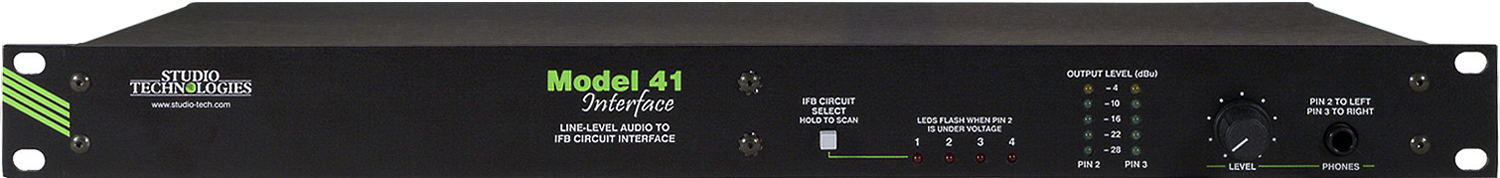
Audio Monitoring
To help confirm proper installation and ensure correct operation, the Model 41 includes a full-featured audio monitor section. Two 5-segment LED meters provide an indication of the audio levels as they appear directly on the IFB output connectors. This capability makes it simple to adjust and maintain correct audio levels so that optimal IFB performance can be achieved. A headphone output is also provided, allowing "real world" checking of IFB audio quality. In addition to being able to manually select the IFB output to be monitored by the meters and headphone output, an "auto scan" mode is also included. This allows each of the four IFB outputs to be monitored in a continuously repeating sequence.
DC Monitoring and Fault Shut Down
To prevent possible damage to the Model 41's output circuitry and connected user devices, the DC output voltage present on pin 2 of each IFB output is continually monitored. If the voltage on an IFB output falls below 24 V its associated LED will "flash" as an error indication. If this under-voltage condition continues for more than four seconds a shut down mode will be entered, turning off power to the IFB output. After a 10-second interval the output will again become active.
Compatibility
The Model 41 is compatible with virtually every digital matrix intercom system, including those from Clear-Com®, RTS®, and Riedel®. Interfacing requires only the connection of analog output ports from the intercom system to the Model 41's audio inputs. Optimal performance will be gained by configuring the nominal audio level of the intercom system's "virtual" IFB output ports to match the Model 41's nominal +4 dBu input level. With the Model 41's excellent audio and power delivery performance it's an ideal alternative to the interface devices offered by the intercom system vendors. Using the Model 41 the intercom system's audio quality can be maintained all the way to the IFB users.
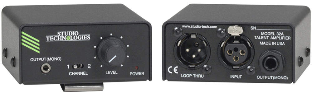
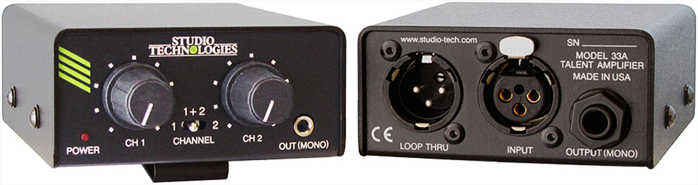
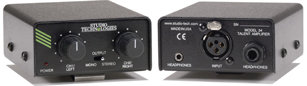
The Model 41's IFB outputs allow virtually every type of IFB user device to be supported. These include the Model 32A, Model 33A, and Model 34 listen-only beltpacks and Model 200-Series announcer console products from Studio Technologies. The 30-series units offer a range of features while providing excellent audio performance. The 200-series units combine a variety of microphone control, headphone monitoring, IFB and intercom system interfacing, and related functions into compact desktop units. Legacy listen-only beltpacks from RTS, including the 4020 and 4030, can also be directly supported.
Alternate Applications
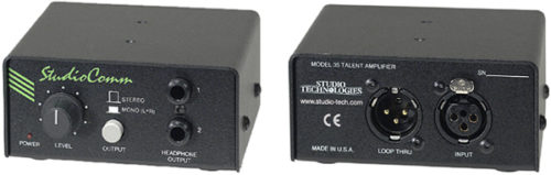
In addition to broadcast intercom applications, the Model 41 can be used to create high-performance stereo headphone cue systems. Line-level signals coming from an audio console, a routing switcher, or an off-air receiver can be connected to the Model 41's audio inputs. The IFB outputs can be connected to listen-only beltpacks, several models of which are available from Studio Technologies. For example, the Model 35 Talent Amplifier will allow one or two pairs of stereo headphones to be supported. Each of the Model 41's four IFB output circuits will support up to six Model 35 Talent Amplifiers.