Announcements
[hsas-shortcode speed="30" direction="left" gap="120"]

Model 240 Producer’s Console

Order Code: M240

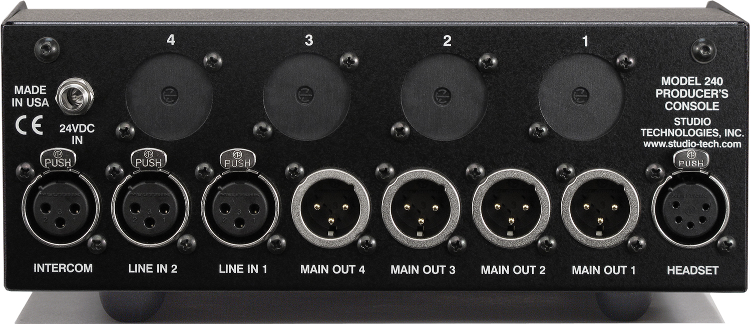
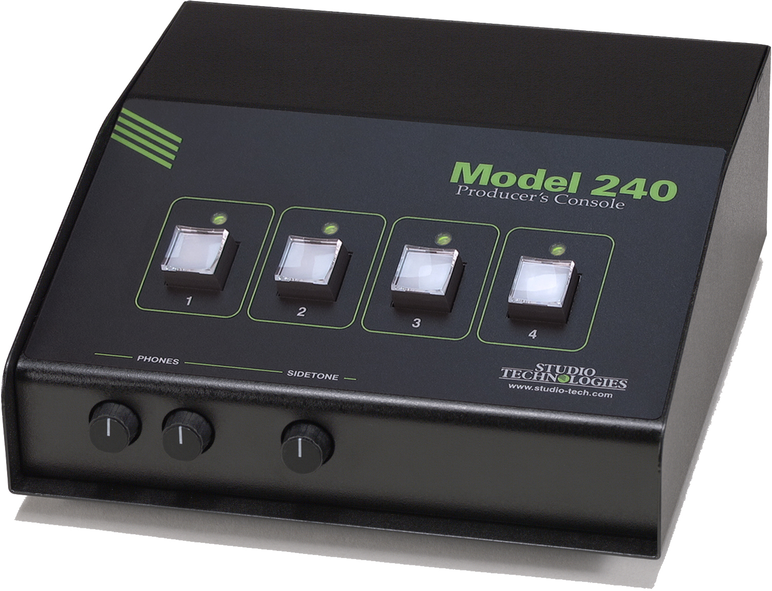
The Model 240 Producer's Console is designed for producers, directors, or those who need to efficiently communicate with on-air broadcast personnel and related production crew. The unit provides the resources of a 4-channel talent cueing ("IFB") central controller combined with a 2-channel party-line (PL) intercom user station. Incorporating numerous configurable features and extensive upgrade flexibility, the Model 240 can meet the exacting demands of this important and highly specialized field. Compatible with broadcast and production audio and intercom system environments, the tabletop unit is well suited for applications including sports and entertainment television programming, radio and TV news, and corporate events. While the Model 240 is sophisticated on the inside, users are presented with a simple-to-use, great sounding "tool" to help them do their job better.

Four pushbutton switches control the routing of microphone audio to the four main outputs and, if selected, the 2-channel PL intercom interface. Each button can be configured for push-to-talk or alternate-action operation. A status LED is located above each button and provides a clear indication of talk status. Two line inputs allow a variety of audio sources to be connected. They can be used as program audio for the four main outputs or routed to the 2-channel headphone output.

Click to expand and read more...

Key Features


Which console is right for your application?
Review the Model 200-Series Feature-by-Feature Comparison Chart.

Documentation Where to Buy

Headset for Microphone and Phones

A 5-pin XLR connector is provided for connection of a broadcast-style headset. The selected headset should contain a dynamic microphone and a single or dual earpiece. While not directly intended for on-air applications, the microphone preamplifier is excellent, providing low-noise, low-distortion, and high headroom performance. For optimal sound quality the gain of the mic preamp can be configured from among five choices. A sophisticated audio compressor circuit follows the microphone preamplifier to minimize the chance of signal overload. The headphone output features low-noise circuitry with plenty of all-important headroom. Many parameters associated with the headphone output can be configured to meet user requirements.

Main Outputs

Four main outputs are provided which can be independently configured to meet the specific needs of broadcast and production applications. They can be, at their most basic, considered talkback channels that, under pushbutton control, contain the signal from the connected headset's microphone. When an additional audio source is selected for use by a main output a composite program/interrupt talent cueing signal is created. Each main output provides a line-level signal that's transformer and capacitor coupled for superior compatibility and reliability. Resistors in series with the output signals allow passive mixing of multiple main output channels. And not to be ignored is the audio quality: clean, quiet, and "click free."

Intercom Interface

The intercom interface is compatible with single- and dual-channel party-line (PL) intercom circuits commonly found in broadcast, production, and industrial applications. Direct connections with PL circuits associated with RTS® TW and Clear-Com® intercom systems is assured. The Model 240 can be configured to serve in a listen-only mode where PL intercom receive audio is routed to the headphone output. Main outputs 3 and 4 can also be independently selected to send talk audio to the intercom circuit. The latter makes the Model 240 function as a full 2-channel intercom user station. The intercom circuit can also provide the power required by the Model 240.

Line-Level Audio Inputs

Two line-level audio inputs allow the connection of a variety of cue signals. The inputs are capacitor and transformer coupled, ensuring consistent and reliable interfacing with almost any audio source found in the field. Two trim potentiometers allow adjustment of the input signal level. The two line inputs can be configured for use with the four main outputs as well as with the headphone output. The four main outputs can be independently configured to use this "program" audio to create talent cue signals. While line input 1 is always assigned to main outputs 1 and 3, the choice of line input 1 or line input 2 is independently assignable to main outputs 2 and 4. Each main output can then be configured for how it uses its associated program audio source. They can be set to have no program audio, continuous program audio that combines with talk audio, program audio that's fully muted when talk is active, or program audio that's "dimmed" (attenuated by 15 dB) when talk is active. In this way four independent "dry" (non-powered) talent cue (IFB) channels can be easily created.

Headphone Output

A 2-channel (stereo) headphone output is provided for monitoring program or intercom audio signals. Physically the headphone output connections are part of the 5-pin XLR headset connector located on the Model 240's back panel. Each headphone output channel can be independently configured to monitor the two line-level inputs or the two intercom interface channels. Two rotary controls allow the user to independently adjust the level of the left and right headphones output channels. A configuration setting allows the headphone output to be placed in monaural mode, mixing the signals selected for the left and right channels. This can be useful when single earpiece ("single-muff") headsets or in-ear transducers are used. A sidetone function is also available, allowing audio from the microphone input to be routed to the left and/or right headphone channels. A separate rotary control is provided for the user to adjust the side-tone level.

Provision has also been made to allow two additional line-level audio sources to be connected and routed to the headphone output channels. Using optional line input cards mounted in the back panel openings of the Model 240, functions such as announcer/commentator pre-fader listen can be implemented.

There may be applications where connecting monitor loudspeakers, rather than a headset or headphones, would be beneficial. This can be easily implemented by installing one or two optional line output cards. A configuration feature allows the headphone output level to be reduced ("dimmed") whenever a talk function is active. This will minimize the chance that acoustical interference and possible feedback will take place between the loudspeakers and the connected microphone.

Relay Contacts

Five normally open (not shorted) solid-state relay contacts are provided as "tally" signals for application-specific use. Four of the contacts are associated with the four talk functions, closing (shorting) whenever a pushbutton switch and associated main output function is active. They can prove useful in applications such as enabling a call light or activating a wireless transmitter. The fifth contact offers a special function, closing (shorting) whenever any of the talk functions are active. This is specifically provided as a "trigger" to mute loudspeaker systems that are located in the same physical area as the Model 240.

Signal Flow

This document can only highlight some of the Model 240's capabilities. For a detailed view of the unit's signal flow it's recommended that the block diagram be reviewed.

Rugged, Flexible, Reliable

The Model 240 uses a rugged desktop enclosure with a removable security plate on the bottom that provides access to the many configuration switches and trim pots. (The unit does not have to be disassembled to be configured!) Laser-engraved on the plate is a complete set of configuration information so that field setup can be fast and accurate. Four openings in back of the Model 240's enclosure allow installation of a variety of option modules. These allow a range of additional features and resources to be easily added for a myriad of potential applications. Numerous 3-pin header connectors are provided on the Model 240's printed circuit board assembly. These provide access to all audio inputs and outputs, along with many special input and output signals. These include four contact inputs associated with the four pushbutton switches. A competent technician can use them to create a highly-customized feature set for meeting the exact needs of specific applications.

The four pushbutton switches associated with the talk functions use gold-plated contacts for reliable long-term operation and include backlighting using white LEDs. A data link allows two Model 240 units to be interconnected as an integrated 2-location system. The status of the talk channels is communicated via the data link; combining of the main output audio signals is done passively. The Model 240 can be powered by an external source of 24 Vdc. Alternately, a connected party-line intercom circuit can provide the required power.

General Audio:
Frequency Response: 20 Hz-20 kHz, +0/–1 dB, mic in/main out
Distortion (THD+N): less than 0.04%, measured at 1 kHz, mic in/main out
S/N Ratio: 87 dB, referenced to –42 dBu mic in/0 dBu main out
Dynamic Range (A-weighted): 113 dB, line in/main out

Microphone Input/Preamplifier:
Type: electronically balanced
Input Impedance: 2 k ohms
CMRR: 83 dB @ 60 Hz, 76 dB @ 20 kHz, 40 dB gain
Gain Range: 35 to 55 dB, adjustable in 5-dB steps
Compatibility: balanced and unbalanced dynamic microphones

Compressor (Microphone Input):
Threshold: 2 dB above nominal level
Attack/Release Time: 2 mSec/100 mSec
Slope: 5:1
Status LED: compressor active

Line Inputs: 2
Type: balanced, transformer-coupled with series capacitors
Impedance: 10 k ohms
Nominal Level: –10 to +6 dBu, adjustable

Main Outputs: 4
Type: transformer-coupled with series capacitors and isolation resistors
Impedance: 600 ohms
Nominal Level: 0 dBu
Maximum Level: +20 dBu, line in/main out

Aux Headphone Line Inputs: 2
Implementation: requires one or two optional line input cards (Studio Technologies order code 31084) to be installed into back panel
Type: balanced, transformer-coupled
Impedance: 10 k ohms, nominal
Nominal Level: +4 dBu

Headphone Output: 1, stereo
Compatibility: intended for connection to mono or stereo headsets or earpieces with nominal impedance of 100 ohms or greater
Type: voltage driver
Maximum Output Voltage: 12 Vpp, 150 ohm load

Intercom Interface:
Type: 2-channel, unbalanced (pin 1 common; pin 2 DC with channel 1 audio; pin 3 channel 2 audio)
Compatibility: single- and dual-channel party-line (PL) intercom systems such as from RTS® and Clear-Com®
Impedance: 10 k ohms
Nominal Receive Level: –10 dBu
Nominal Talk Level: –10 dBu
Sidetone (Null): 0 to –18 dB, adjustable

Relay Contacts: 5
Functions: one each follows main output status and one any talk active
Contacts: form A (normally open, not shorted)
Rating: 100 mA, 60 V AC/DC, maximum
Contact Resistance: 16 ohms, maximum
Access: requires user-implemented connector scheme

Remote Switch Inputs: 4
Functions: mimics the action of the four pushbutton functions
Type: active low, 0.5 mA maximum, inputs pull up to 5 volts DC

Multi-Unit Support: Two units can be interconnected via internal RS-485 data bus. Audio summing is performed passively using external wiring.

Power Sources:
Intercom Interface: 24-32 Vdc, 150 mA
External: 20-30 Vdc, 125 mA @ 24 Vdc. Each unit shipped with a universal input/24 Vdc output power supply.

Connectors:
Line Inputs, Intercom Interface: 3-pin female XLR
Main Outputs: 3-pin male XLR
Headset (mic/phones): 5-pin female XLR
24 Vdc Power In: 2.1 x 5.5 mm coaxial power jack with locking bushing, compatible with Switchcraft S760K plug

Spare Connector Locations: 4
For use by Studio Technologies' wide range of option modules. Also allows up to four Neutrik NC*D-L-1 connectors to be installed (*=3F, 3M, etc.).

Dimensions (Overall):
8.1 inches wide (20.6 cm)
3.3 inches high (8.4 cm)
8.5 inches deep (21.6 cm)

Weight: 4.5 pounds (2.0 kg)

Specifications subject to change without notice.

Documentation

Data Sheet  

Title
Model 240 Producer's Console Data Sheet
Description
Issue 1
Release Date
01-Aug-2013

User Guide  

Title
Model 240 Producer's Console User Guide
Description
Issue 2
S/N Range
00151-later
Firmware
2.1-higher
Release Date
01-Jun-2016

Block Diagram  

Title
Model 240 Producer's Console Block Diagram
Description
Revision B
S/N Range
00151-later
Release Date
02-May-2013

Other Documentation  

Title
Model 240 Producer's Console Configuration Guide
Description
Issue 1
S/N Range
00151-later
Release Date
01-Aug-2013
Title
Model 200-Series Comparison Chart
Description
Issue 23
Release Date
06-Jun-2023
Title
Model 200-Series Assemblies, Card Kits, and Accessories
Description
Issue 13
Release Date
15-Feb-2023
Title
Model 200-Series Accessories Installation & Configuration Guide
Description
Issue 22
Release Date
25-Apr-2023

Images  

Model 240 Producer's Console Front Angle View
Model 240 Producer's Console Rear View
Model 240 Producer's Console Bottom View with Security Panel Attached
Model 240 Producer's Console Bottom View with Security Panel Removed showing Configuration Switches and Trim Potentiometers
Skip to content
Menu