Live-Link Jr. General Specifications
SDI Compatibility, Supported Resolutions, and Rates:
SD-SDI per SMPTE ST® 259:2008:
525i: 59.94
625i: 50
HD-SDI per SMPTE ST 292:2011:
720p: 50, 59.94, 60
1080i: 50, 59.94, 60
1080p: 23.98, 24, 25, 29.97, 30
1080psf: 23.98, 24
3G-SDI Level A per SMPTE ST 424:2006 and ST 425:2011:
1080p: 50, 59.94, 60
Audio, Data, GPI/GPO, and Control Data Transport:
Embedded into SD-SDI as HANC Ancillary Data per SMPTE ST 272:2004 and ST 291:2011.
Embedded into HD-SDI as HANC Ancillary Data per SMPTE ST 291:2011 and ST 299:2009.
Embedded into 3G-SDI as HANC Ancillary Data per SMPTE ST 291:2011, ST 299:2009, and ST 425:2011.
SDI Inputs and Outputs:
Type: unbalanced
Impedance: 75 ohms
Level: 800 mV p-p, nominal
Optical Interface: quantity 2 single-mode fibers
Optical Outputs:
Compliance: SMPTE ST 297:2006 (as applicable)
Fiber Type: single mode
Wavelength: 1310 ±20 nm (FP laser)
Launch Power: –3 dBm, nominal
Typical Fiber Interconnect Length: 10 km minimum
Optical Inputs:
Compliance: SMPTE ST 297:2006 (as applicable)
Fiber Type: single mode
Wavelengths Supported: 1250 to 1650 nm
Receive Sensitivity: –17 dBm, nominal @ 2.97 Gb/s
Maximum Input Power: –3 dBm, nominal
Audio, Mic/Line Input to Mic/Line Output:
Frequency Response: +0/–0.35 dB, 20 Hz to 20 kHz
Distortion (THD+N): 0.003%, measured at 1 kHz
Dynamic Range: 109 dB
Audio, Line/IFB Input to Line Output:
Frequency Response: ±1 dB, 20 Hz to 20 kHz
Distortion (THD+N): 0.01%, measured at 1 kHz
Dynamic Range: 101 dB
Audio, 4-Wire Input to Party-Line Intercom Pin 3:
Frequency Response: ±1.25 dB, 100 Hz to 10 kHz (band limited for optimal performance)
Distortion (THD+N): 0.02%, measured at 1 kHz
Dynamic Range: 99 dB
Party-Line Hybrids:
Topology: 3-section analog circuitry compensates for resistive, inductive, and capacitive 2-wire party-line loads
Nulling Method: automatic upon user initiation, processor implements digital control of analog circuitry; settings stored in non-volatile memory
Nulling Line Impedance Range: 120 to 240 ohms
Trans-Hybrid Loss: >45 dB, typical at 1 kHz
Data Transport:
RS-422, full duplex, asynchronous (serial)
Rate: auto-sensing, 115.2 kb/s, maximum with HD- or 3G-SDI (57.6 kb/s with SD-SDI)
GPI/GPO Transport:
GPI Input: +3.3 Vdc logic, activates on closure to system common
GPO Output: normally open, isolated, solid-state relay contact, 60 Vdc maximum, 400 mA maximum
Auxiliary Power Source: 5.5 Vdc, 40 mA maximum
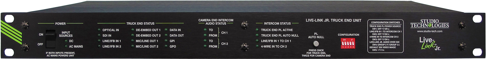
Live-Link Jr. Truck End Unit Specifications
Line/IFB and 4-Wire Intercom Inputs:
Type: analog, electronically balanced, capacitor-coupled, 20 k ohms
Nominal Level: +4 dBu
Maximum Level: +24 dBu
De-Embed, Mic/Line, and 4-Wire Intercom Outputs:
Type: analog, electronically balanced, capacitor-coupled, intended to drive balanced loads of 2 k ohms or greater
Source Impedance: 200 ohms
Nominal Level: +4 dBu
Maximum Level: +24 dBu into 10 k ohms
Party-Line Intercom Interface:
Type: 2-channel party-line, unbalanced (common on pin 1, DC modulated with channel 1 audio on pin 2, channel 2 audio on pin 3)
Compatibility: dual-channel intercom system such as from RTS®
Nominal Audio Level: –10 dBu
Maximum Audio Output Level:
Pin 2: +9 dBu
Pin 3: +10 dBu
Output Voltage (Pin 2 to Pin 1): 29 Vdc, selectable on/off
Output Current (Pin 2 to Pin 1): 300 mA maximum; requires ≥10 mA current draw for detection of connected device
Impedance (Pin 2 to Pin 1; Pin 3 to Pin 1), Local Party-Line Power Enabled: 200 ohms
Impedance (Pin 2 to Pin 1; Pin 3 to Pin 1), Local Party-Line Power Disabled: >10 k ohms
Connectors for Electrical Signals:
SDI: BNC, 3G-SDI optimized, gold plating on center pin, per IEC 61169-8 Annex A
Line/IFB and 4-Wire Intercom Inputs: 3-pin female XLR
De-Embed, Mic/Line, Party-Line Intercom, and 4-Wire Intercom Outputs: 3-pin male XLR
Data, GPI/GPO, and Auxiliary DC: 9-pin female D-subminiature (DE-9F)
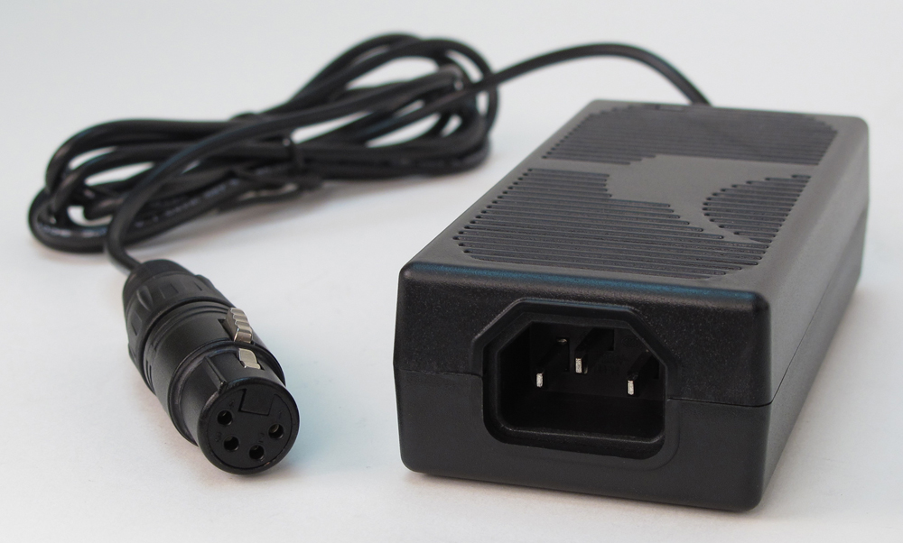
DC Input: 4-pin male XLR
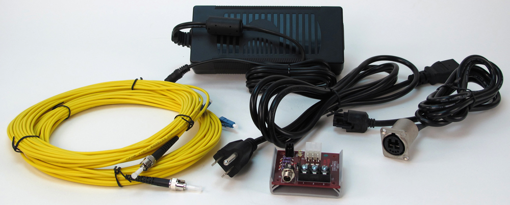
AC Mains Input: 3-blade, IEC 320 C14-compatible (mates with C13)
Optical Connectors: two ST (UPC polish)
Power Inputs:
AC Mains: 100 to 240 V, 50/60 Hz, 24 W maximum
DC: 10 to 18 V, 2.0 A maximum
Dimensions (Overall):
19.00 inches wide (48.3 cm)
1.72 inches high (4.4 cm)
8.7 inches deep (22.1 cm)
Mounting: one space (1U) in a standard 19-inch rack
Weight: 3.9 pounds (1.8 kg)
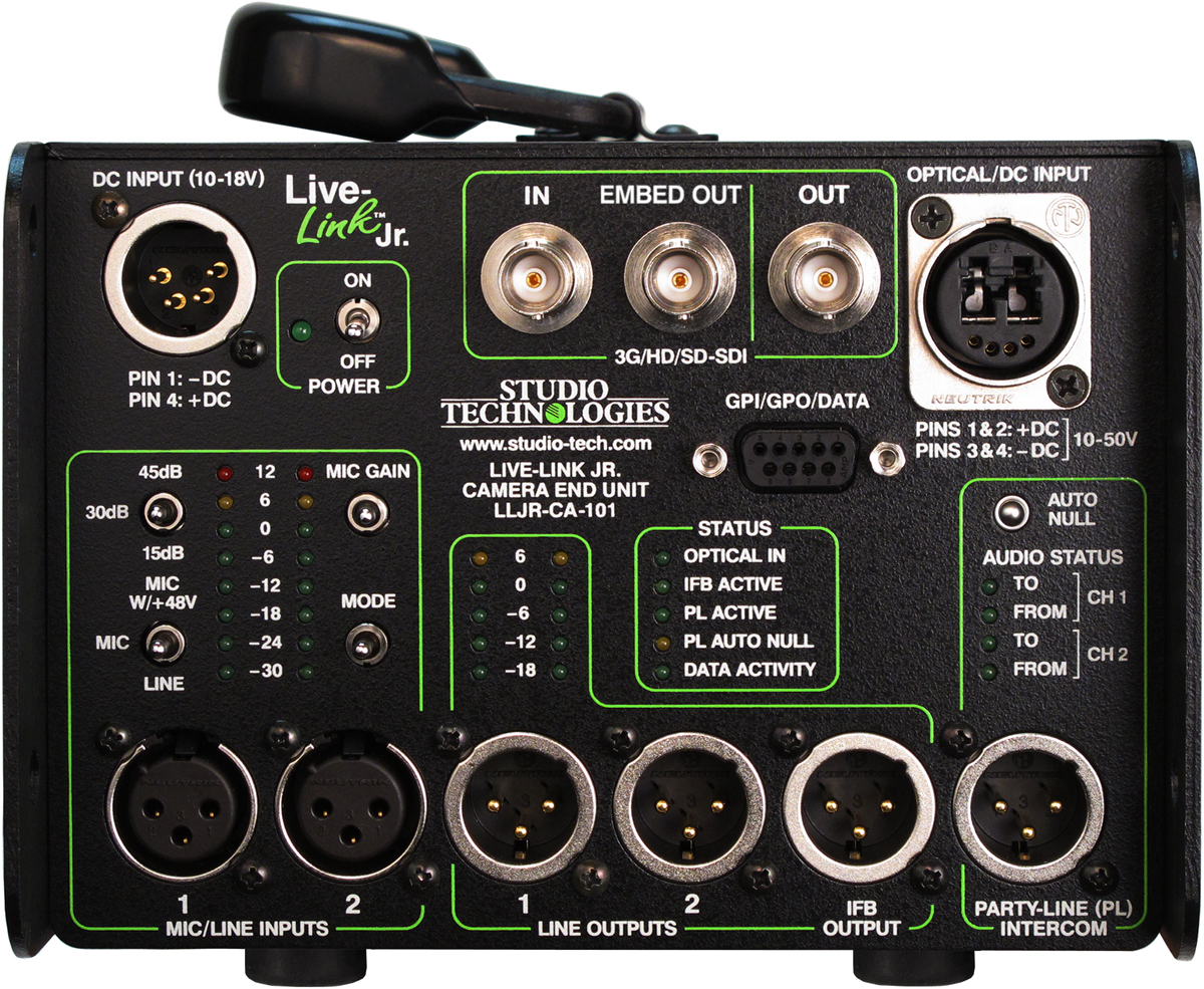
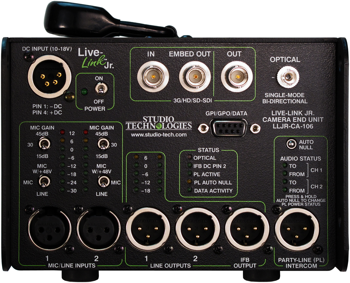
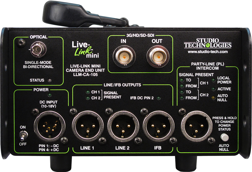
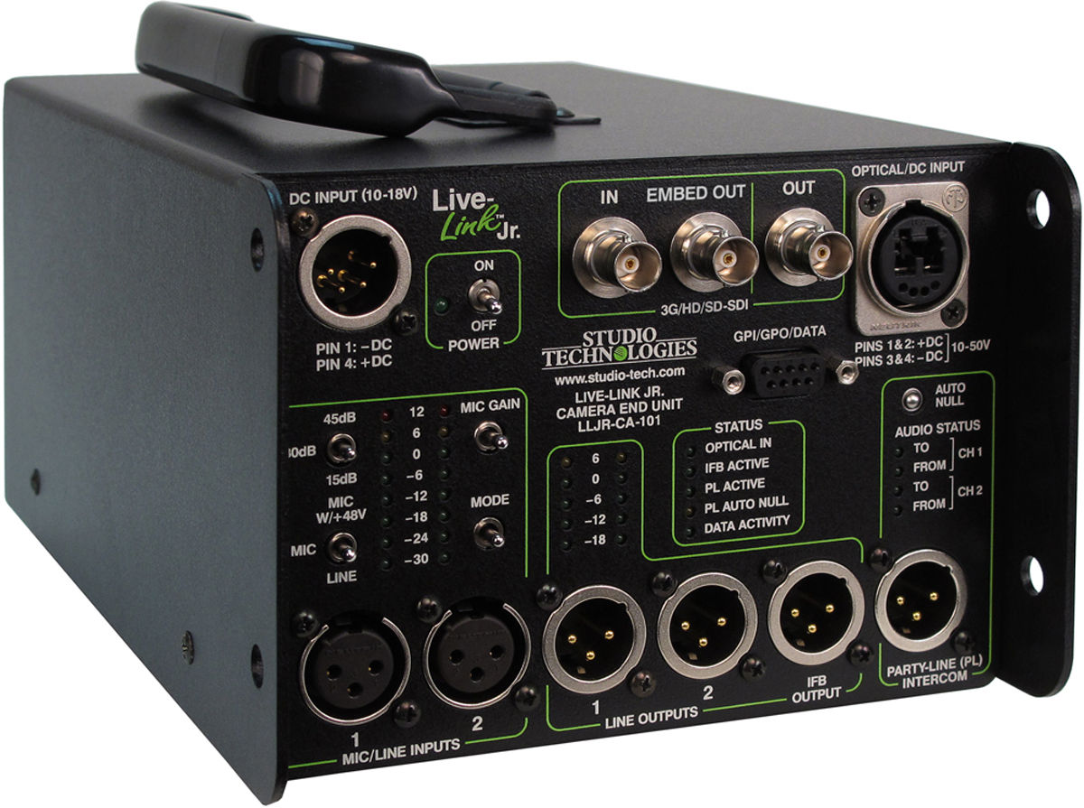
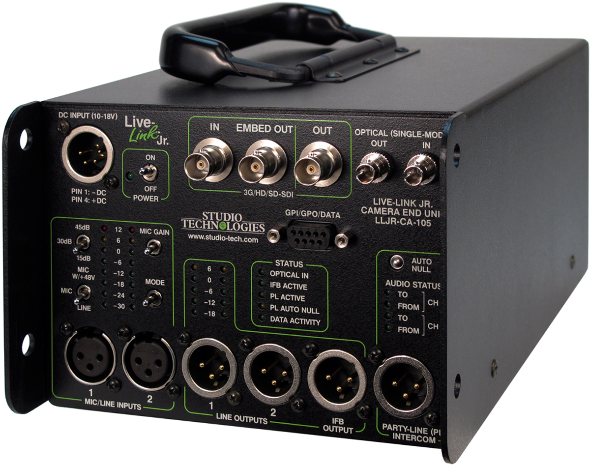
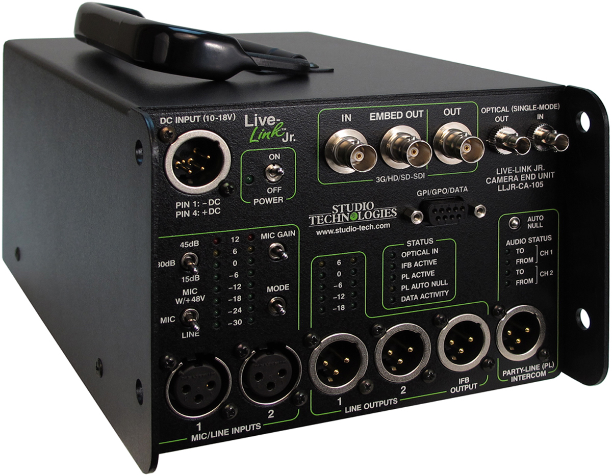
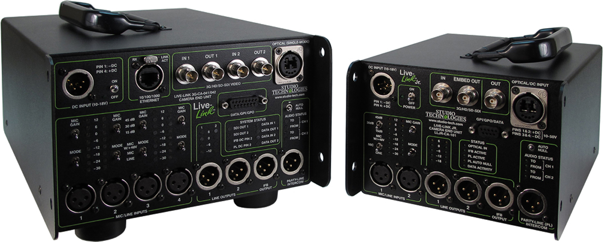
Live-Link Jr. Camera End Unit Specifications
Mic/Line Inputs:
Input Sensitivity: selectable for line level (unity gain), 15, 30 or 45 dB gain
Maximum Input Level: +24 dBu
Type: electronically balanced
Impedance: approximately 3 k ohms
CMRR: 61 dB at 60 Hz
Phantom Power: 48 Vdc, meets IEC 61938 P48 standard
Line Outputs:
Type: analog, electronically balanced, capacitor-coupled, intended to drive balanced loads of 2 k ohms or greater
Source Impedance: 200 ohms
Nominal Level: +4 dBu
Maximum Level: +24 dBu into 10 k ohms
IFB Output:
Type: 2-channel unbalanced (common on pin 1, DC modulated with channel 1 audio on pin 2, channel 2 audio on pin 3)
Nominal Audio Level: –10 dBu
Maximum Audio Output Level:
Pin 2: +9 dBu
Pin 3: +10 dBu
DC Output Voltage (Pin 2 to Pin 1): 28 V
DC Output Current (Pin 2 to Pin 1): 130 mA maximum
Impedance (Pin 2 to Pin 1; Pin 3 to Pin 1): 200 ohms
Party-Line Intercom Interface:
Type: 2-channel party-line, unbalanced (common on pin 1, DC modulated with channel 1 audio on pin 2, channel 2 audio on pin 3)
Compatibility: dual-channel intercom system such as from RTS®
Nominal Audio Level: –10 dBu
Maximum Audio Output Level:
Pin 2: +9 dBu
Pin 3: +10 dBu
Output Voltage (Pin 2 to Pin 1): 28 Vdc
Output Current (Pin 2 to Pin 1): 200 mA maximum; requires ≥10 mA current draw for detection of connected device
Impedance (Pin 2 to Pin 1; Pin 3 to Pin 1): 200 ohms
Connectors for Electrical Signals:
SDI: BNC, 3G-SDI optimized, gold plating on center pin, per IEC 61169-8 Annex A
Mic/Line Inputs: 3-pin female XLR
Line, IFB, and Party-Line Intercom Outputs: 3-pin male XLR
Data, GPI/GPO, and Auxiliary DC: 9-pin female D-subminiature (DE-9F)
DC Input: 4-pin male XLR
Optical Connector(s): Neutrik® opticalCON® DUO or two ST (UPC polish), factory installed, selectable at time of order
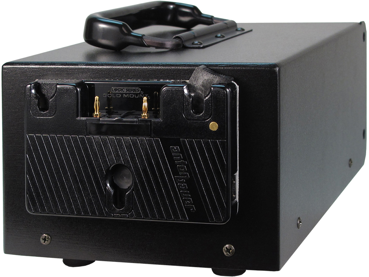
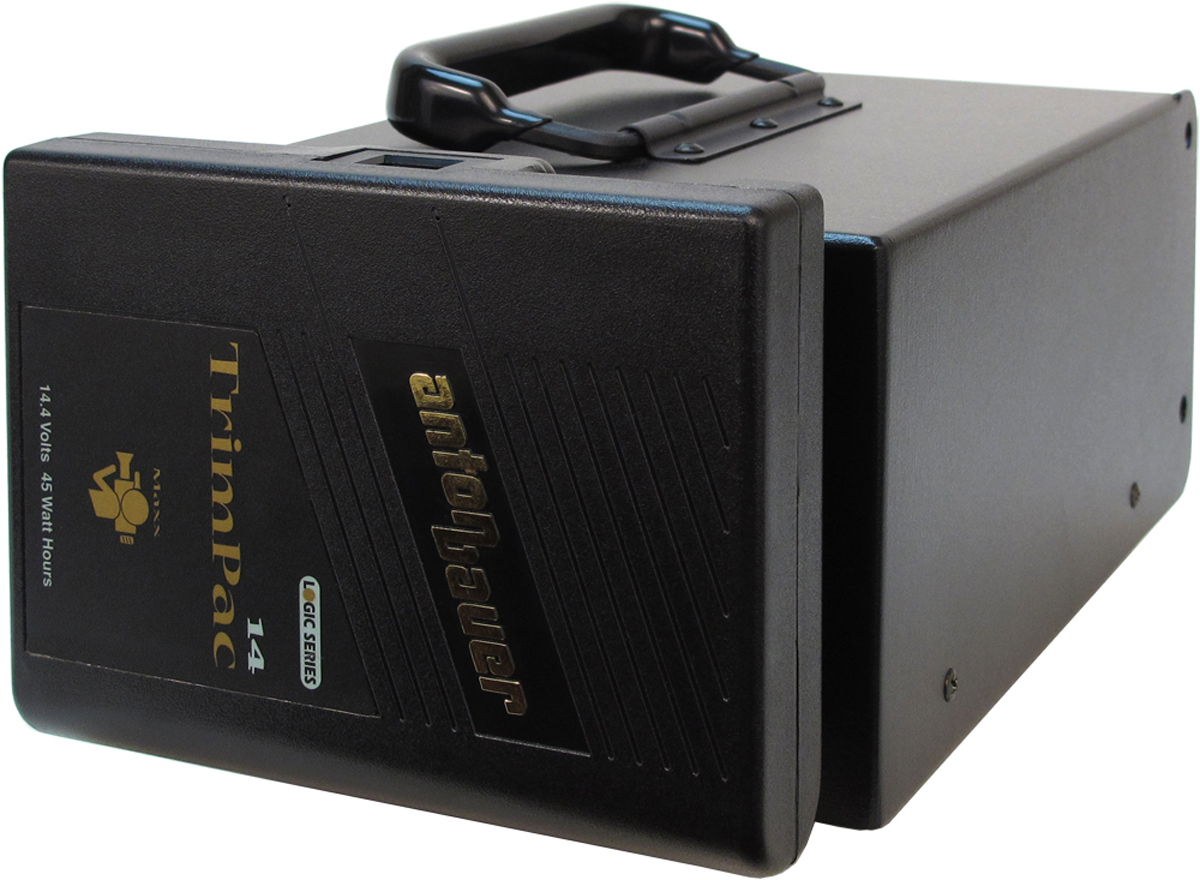
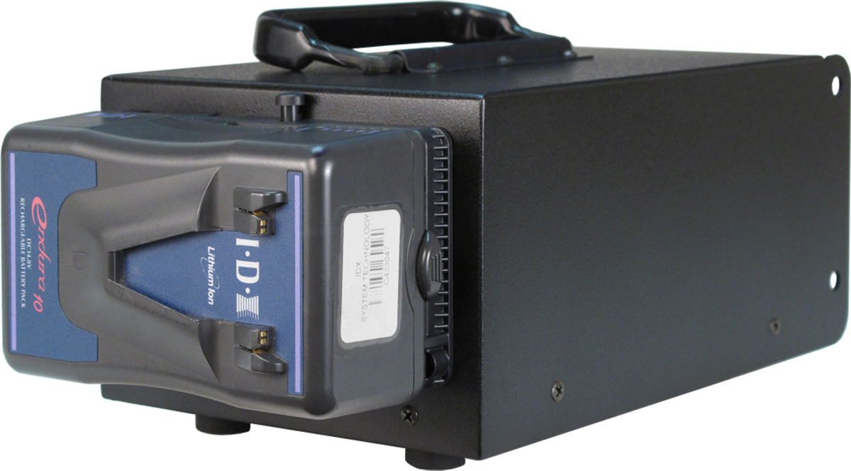
Battery Mounting: Anton/Bauer® QRC-Gold®, standard; IDX® P-V2 V-Mount, optional
Power Inputs:
DC (4-Pin XLR) and Battery Mount: 10 to 18 Vdc, 1.9 A maximum at 12 V; 2.1 A at 10 V
Copper/Optical Hybrid via opticalCON DUO: 10-50 Vdc, 0.54 A maximum with 48 V source and 500 feet (154 meters) of two 16 gauge copper conductors, maximum length TBD
Dimensions (Overall):
6.5 inches wide (16.5 cm)
5.7 inches high (14.5. cm)
10.4 inches deep (26.4 cm)
Weight: 5.5 pounds (2.5 kg)
Specifications subject to change without notice.