The Models 76 and 76B Central Controllers were manufactured for a number of years but were discontinued in August of 2012 due to parts availability and decrease in demand. They were excellent products, most of which are still in use by many facilities. We have become aware that after ten or more years of field operation an oscillation in the range of 17-18 kHz can appear in the units’ analog output channels. It was found that the units’ –15 volts DC power supply “rail” or “bus” can start oscillating due to an electrolytic capacitor aging and becoming ineffective in its bypass function. At the time of manufacture, Studio Technologies used a high-quality 47 uF, 25 volts, surface mounted, electrolytic capacitor (Studio Technologies’ part number 4975) for this purpose. Unfortunately, this part has been shown to not “age” well in all cases which can lead to issues.
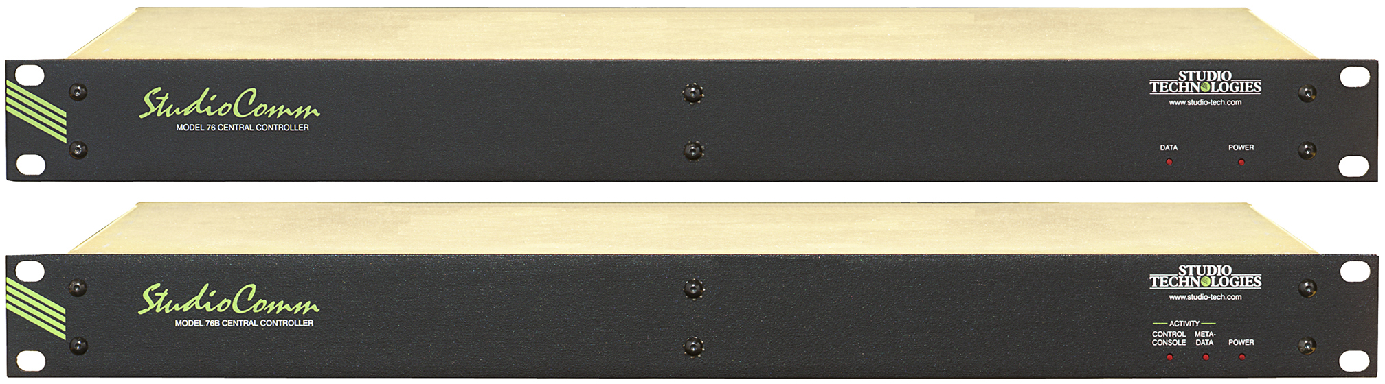
Model 76 Central Controller and Model 76B Central Controller
A competent technician is required to perform any repairs or updates to the Model 76 or Model 76B. Before any action is taken, the designated unit must be removed from an equipment rack and its source of AC mains power must be disconnected from the back-panel connector.
After AC mains power has been disconnected from the Model 76 or Model 76B then the cover can be removed. Once this has been performed the revision level of the unit’s circuit board can be identified. From the revision level the bypass capacitor in need of changing can be identified. For revision B circuit boards the capacitor has a reference designator shown on the circuit board’s solder mask (in white text) of C193. For revision C circuit boards the capacitor has the reference designator C196. Changing this one capacitor will typically resolve the oscillation issue. Replacement 47 uF, 25 V parts should be readily available from sources such as Digi-Key and Mouser. Specific parts that will fit directly and function correctly include the Panasonic FK-Series, EEE-FK1E470P (Digi-Key PCE3804, Mouser 667-EEE-FK1E470P) and the Nichicon UUD-Series, UUD1E470MCL1GS (Digi-Key 493-2273-2, Mouser 647-UUD1E470MCL).
At the time of Model 76 and Model 76B manufacture, four identical 47 uF, 25 V, capacitors were used. There is no reason that all four can’t be changed to ensure that aging of these capacitors won’t cause any future problems. (Although only the one used for bypassing the –15 volts DC rail seems to have caused an operational issue.) For revision B circuit boards one would change C36, C73, C178, and C193 with, as previously noted, C193 being the bypass capacitor for the –15 volts DC rail. For revision C circuit boards one would change C39, C76, C181, and C196 with the latter being the bypass capacitor for the –15 volts DC rail.
A very simple means of confirming the issue and, if desired, implementing a permanent solution would be to install (solder in) a leaded electrolytic capacitor between the –15 volts DC test point and the common test point. These are located on both revisions of the circuit board near the –15 volts DC 3-terminal regulator parts and clearly marked in white legend. An axial-leaded 47 uF, 25 volt electrolytic capacitor would be ideal. A part with radial leads could also probably be installed without an issue. (Any capacitor with a value of 33, 47, 68, or 100 uF and a rating of 25, 35, or 50 volts should be acceptable.) Installing such a leaded part, without removing the existing surface-mount bypass capacitor, should resolve an oscillation issue on the –15 volts DC rail. If this leaded part is to be permanently left in place, it should be secured to the circuit board using an appropriate non-conductive adhesive (such as RTV silicone). Be very careful to observe the capacitor’s polarity when it is being installed. Since a negative rail is going to be bypassed the capacitor’s positive (+) lead will be connected to the common test point!
Once a permanent solution has been implemented it’s probably a good idea to monitor each of the Model 76 and Model 76B’s DC rails with an oscilloscope. The DC voltages should be “clean” with a minimal amount of AC ripple voltage present.