This discussion relates to the topic of antennas and cabling that may be utilized in conjunction with a Studio Technologies, Inc. Model 5402 Dante Leader Clock with GNSS Synchronization.
We’ll begin by citing Google’s AI Overview of GNSS:
GNSS, or Global Navigation Satellite System, refers to any satellite constellation that provides global positioning, navigation, and timing services. It’s a technology that allows users to determine their location on Earth using signals from multiple satellites. While often associated with GPS, GNSS encompasses various satellite systems like GPS (US), GLONASS (Russia), Galileo (EU), and BeiDou (China).
Recently the subject of antenna type and interconnecting cable length as related to the Model 5402 Dante Leader Clock with GNSS Synchronization has arisen. Studio Technologies’ technical personnel have done some experimentation related to this subject with the results provided in the following paragraphs.
-
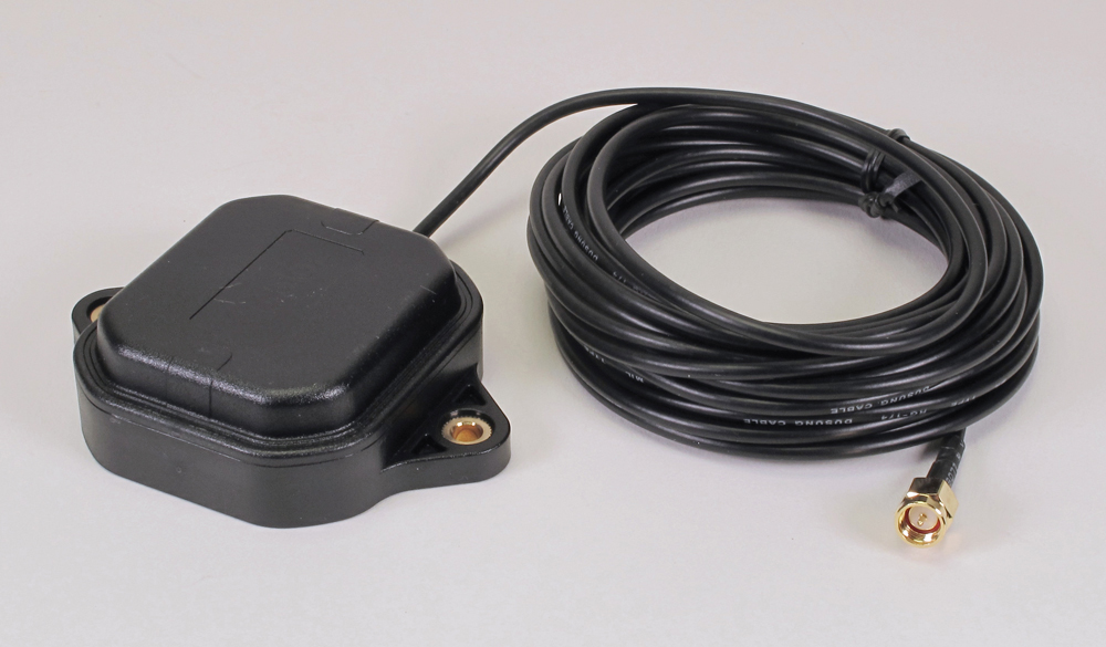
ublox ANN-MB-01 multi-band, high-precision GNSS antenna with attached 5-m (16.4-ft) cable
The Model 5402 utilizes GNSS connectivity for timing support; it’s referred to as being able to “sync” to a GNSS timing source. However, technically it’s probably more accurate to say that GNSS-obtained timing signals are used to discipline the Model 5402’s internal clock source. From the factory, each Model 5402 ships with a GNSS antenna. This antenna (ublox ANN-MB-01) includes a permanently attached 5-meter (16.4-foot) length of RG174 miniature coaxial cable terminated with an SMA male connector. This connector is compatible with the SMA female bulkhead connector that is located on the Model 5402’s back panel. The included antenna is rated for outdoor use and allows for both magnetic and M4 machine screw mounting. While this antenna has the “look and feel” of a consumer-type, it’s actually quite good in quality and has been used successfully in many Model 5402 applications.
-
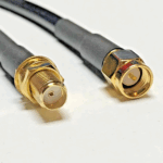
6-m (19.7-ft) extension coaxial cable
A customer wanted to extend the Model 5402’s GNSS antenna from its standard 5-meter (16.4-foot) cable length to 10 meters (32.8 feet). From eBay, a 6-meter (19.7-foot) extension cable was obtained. This cable used RG174 coaxial cable which was terminated with an SMA male connector on one end and an SMA female connector on the other. Testing this arrangement resulted in successful Model 5402 GNSS performance. As a convenience, Studio Technologies decided to offer this cable as an accessory with the part number 13716. (Contact the factory for price and availability details.)
- Another customer wanted to roof-mount a GNSS antenna that would be located 150 feet (45.7 meters) away from a Model 5402. While the standard antenna and a 135-foot (45-meter) extension cable might be functional, it was not the recommended solution. The gain of the standard antenna, along with its cable attenuation, may provide marginal performance.
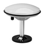
Roof-mounted STARF STA-107 high-gain GPS antenna

From a vendor in China who had listed products on eBay, a STARF STA-107 High-Gain GPS Antenna antenna was obtained. This roof-mounted antenna is designed to receive satellite signals in the L1 and L2 bands and is advertised to support GPS, GLONASS, Galileo, and BeiDou constellations. Its impedance is 50 ohms and incorporates an LNA amplifier with a nominal gain of 40 dB (which is approximately 20 dB greater than the standard antenna and permanently attached 5-meter cable). The STA-107 has a very nice nice overall “fit and finish” and incorporates a TNC female connector on its bottom surface.
A compatible interconnecting cable was obtained from American Coaxial Industries (ACI) through their listings on eBay. They fabricated a cable to meet the application’s needs using 150 feet (45.7 meters) of low-loss coaxial cable (ACI type 240) with a TNC male connector on one end and an SMA male connector on the other. Using this cable assembly, the STA-107 antenna was interconnected with a Model 5402. This arrangement resulted in successful performance of the Model 5402 which was able to “sync” to multiple satellite constellations.
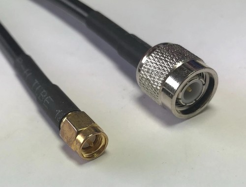
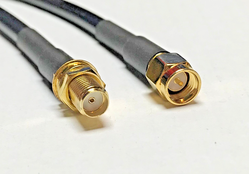
45-ft (13.7-m) ACI type 200 cable
Additional testing was performed with the STA-107 to try to determine a cable length limit. Three 45-foot (13.7-meter) “extender” cables were obtained from ACI. In this case, the ACI type 200 cable was utilized with an SMA male connector on one end and an SMA female connector on the other. One, two, and all three of the 45-foot (13.7-meter) cable assemblies were consecutively added to the 150-foot (45.7 meter) cable while testing for correct GNSS operation. In all three cases, the Model 5402 continued having GNSS success. The ability to utilize these three extension cables, giving a maximum total cable length of 285 feet (86.9 meters) with multiple connectors involved, was impressive. This overall cable length and connector arrangement should prove to be more than sufficient for most Model 5402 applications.
While testing and experimentation related to this subject was very interesting, the reality is that trying an antenna, an interconnecting cable, and a Model 5402 together prior to deployment is really the best way of determining if the actual performance will be as required.