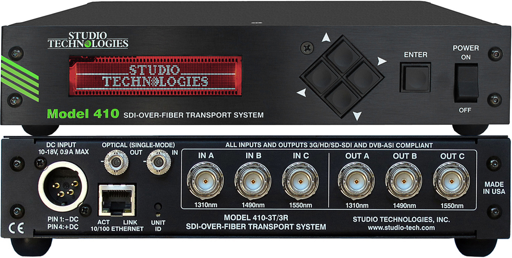
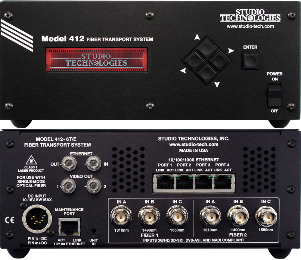
The Model 400 SDI-Over-Fiber Transport System consists of single-rack-space (1U) units that are factory configured from among a number of available choices. The broad range of configurations allows the needs of specific applications to be directly supported. For example, the Model 400-12T is a 12-channel electrical-to-optical (E2O) unit, while the Model 400-12R is a 12-channel optical-to-electrical (O2E) unit. For "transceiver" applications the Model 400-3T/3R provides three channels of electrical-to-optical (E2O) and three channels of optical-to-electrical (O2E) transport. The front panel of each unit features a day-/night-readable color backlit display, menu navigation buttons, status LEDs, and power on/off switch. The back panels include connections for AC mains and DC power, ST or SC (optional) optical connectors, BNC connectors, and an RJ45 jack for the Ethernet interface.
Technology
The Model 400 System uses a novel hardware implementation to transport up to 12 SDI signals over four single-mode optical fibers. The Model 400-12T's 12 SDI inputs are arranged as four groups, with each group of three SDI signals being transported over one fiber at wavelengths of 1310, 1490, and 1550 nm. In typical applications the launch power is such that signals can be transported over a minimum distance of 10 kilometers.
SDI input signals can be SD (270 Mb/s), HD (1.485 Gb/s), or 3G (2.97 Gb/s). 3G signals can be in either Level A or Level B format. The inputs also support video signals in the DVB-ASI (270 Mb/s) format. Each of the Model 400's SDI input channels is independent, allowing any combination of rates/formats to be transported.
Associated with each Model 400 SDI input channel is a re-clocked and buffered loop-through output. These can be extremely useful, allowing a signal source to be routed to another input on the Model 400 or a related piece of equipment.
Typically a Model 400-12R receives the four single-mode fiber signals that originate in a Model 400-12T. Each optical input is de-multiplexed into three optical channels which are converted into electrical signals. Each of these SDI signals are then re-clocked and sent to two independent SDI output drivers. As such, the Model 400-12R has 24 (12 pairs) of BNC output connectors.
Dual Power Capability
Model 400 units allow an AC mains source of 100-240 V, 50/60 Hz to be directly connected. They can also be DC powered using a 10-18 volt source that is connected via a broadcast-standard 4-pin XLR connector.
If both AC and DC power sources are connected to a Model 400, the unit will be powered by the AC mains supply. Only if the AC mains source fails will a load be placed on the DC source. This allows a source of DC, typically a battery pack, to serve in a backup capacity. With this arrangement normal SDI-over-fiber transport operation can continue even if AC mains power is lost.
Remote Monitoring and Configuration
The Model 400 has an embedded web server that allows the user to monitor system status through any web-enabled device such as a personal computer or smartphone. System status can also be communicated using SNMP, making it possible to integrate the unit's monitoring information into a networked alarm and control software application.
The Model 400's status screen lets a user or supervisor check for the presence of AC and DC power sources as well as individual SDI input channel status, signal rate, and whether the optical transmitters are enabled. The optical output power of each electrical-to-optical (E2O) channel is reported directly in dBm. The optical receive power (in dBm) of each optical-to-electrical (O2E) channel is also displayed. This is a particularly useful feature for remote system troubleshooting.
The embedded web server also provides a configuration menu allowing a variety of monitoring parameters to be set. These include alarms for loss of AC or DC power, over-temperature, and low optical transmit and receive levels. Additional menu screens provide access to SNMP, network IP address, and front-panel display configurations. Advanced features include the ability to remotely update the Model 400's system firmware via the Ethernet connection.
Simple Installation
While the Ethernet-accessed monitoring and configuration functions enhance the utility of the Model 400 they are not necessary for SDI-over-fiber transport operation. Model 400 units will deliver reliable, high-quality performance with no other user actions except for making SDI-over-coaxial cable, fiber, and power connections. All back-panel connectors are clearly labeled for simple, fast, and intuitive use. And the front-panel display provides direct access to the unit's most important status information.


