Applications for the Model 5121 include sports broadcasting booth packages, remote news gathering "fly-packs," stadium audio/video interface (I/O) locations, and other broadcast-infrastructure projects. The number of Model 5121 modules used in a project can vary widely—from one to dozens. In each case the Model 5121's performance will be completely "pro" with audio quality, reliability, and installation flexibility matching that of larger-scale audio consoles, matrix intercom systems, and stand-alone IFB systems.
Typical applications will find either or both of the Model 5121's analog or digital audio inputs being interfaced with outputs provided by fiber-optic transport modules, audio/video routers, broadcast/production consoles, and matrix intercom systems. Only one of the audio inputs, analog or digital, will be used at any one time. No mixing of the signals will take place. While both physical inputs can be connected, by default the digital audio input will always take precedence. In the automatic selection mode the digital audio input will serve as the Model 5121's audio source should it be present and "locked" to the input circuitry. The analog audio input will be active whenever a digital audio signal is not present and "locked."
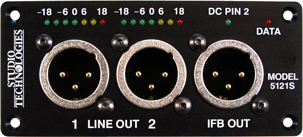
he Model 5121's line-level outputs would typically be connected to battery-powered listen-only headphone amplifiers, amplified speakers, or inputs on broadcast media storage systems. In remote-broadcast applications these two outputs may be referred to as "dry" (no DC voltage present) IFB signals. The Model 5121's IFB output is directly compatible with listen-only portable IFB amplifiers, such as the Models 32A, 33A, or 34A from Studio Technologies, Inc. The 2-channel IFB output provides signal common on one pin, +28 volt DC power with superimposed channel 1 audio on a second pin, and channel 2 audio only on a third pin. This complies with a long-popular broadcast-standard implementation.
Model 5121 Line/IFB Output Modules do not include a mounting enclosure or chassis. They are intended for mounting in custom 19-inch rack panels, equipment boxes, broadcast furniture, "NEMA" I/O boxes, or other specialized enclosures. It is expected that integration firms will create applications that use Model 5121 modules as part of complete broadcast, production, corporate, and government solutions. Sophisticated users will be able to create "one-off" solutions to solve unique challenges.
Separate audio inputs are provided for interfacing with analog and digital audio sources. The two analog inputs are balanced and compatible with line-level signals. An unbalanced AES3 digital audio input allows the connection of two audio channels. By default, input source selection is automatic. If an AES3 digital audio source is connected it will have priority. Two 7-segment LED meters provide the user with an indication of the input levels.
The Model 5121's audio performance is very good. Low-noise, wide dynamic-range circuitry ensures that the input audio quality is preserved. The audio source connected by way of the digital audio input is routed to a high-performance digital-to-analog converter (DAC) section that supports sample rates of up to 48 kHz with a bit depth of up to 24. The two audio signals coming from the analog inputs or the DAC circuitry are routed to two line-level analog audio output sections. These provide the line-level, balanced, ESD-protected, capacitor-coupled output signals.
The two signals coming from the active audio input channels are also routed to the IFB circuitry. One channel is used to amplitude modulate the DC power source circuitry. The second channel is routed to a single-ended (unbalanced) line-driver circuit. The IFB circuitry provides a low-noise, current-limited source with a nominal 28 volt DC output. This is essentially identical to that created by "big time" broadcast IFB systems. Logic circuitry contained within the Model 5121 monitors the DC output voltage. Should a low-voltage/over-current condition be detected the DC output enters a protection mode. Once the fault condition is removed normal operation will again resume. An LED, located on the Model 5121's front panel, provides an indication of the IFB output's status. Note that for additional flexibility, the source impedance of the IFB output channels is 200 ohms. This allows intercom user beltpacks to serve as listen-only devices as well as functioning as a small party-line intercom system.
All audio inputs and outputs were carefully designed for use in permanent as well as field applications. Filtering on the analog audio inputs minimizes the chance that radio frequency (RF) energy will interfere with audio input sources. Other components were included to address ESD ("static") and DC over-voltage conditions The DC power input is protected from accidental polarity reversal.
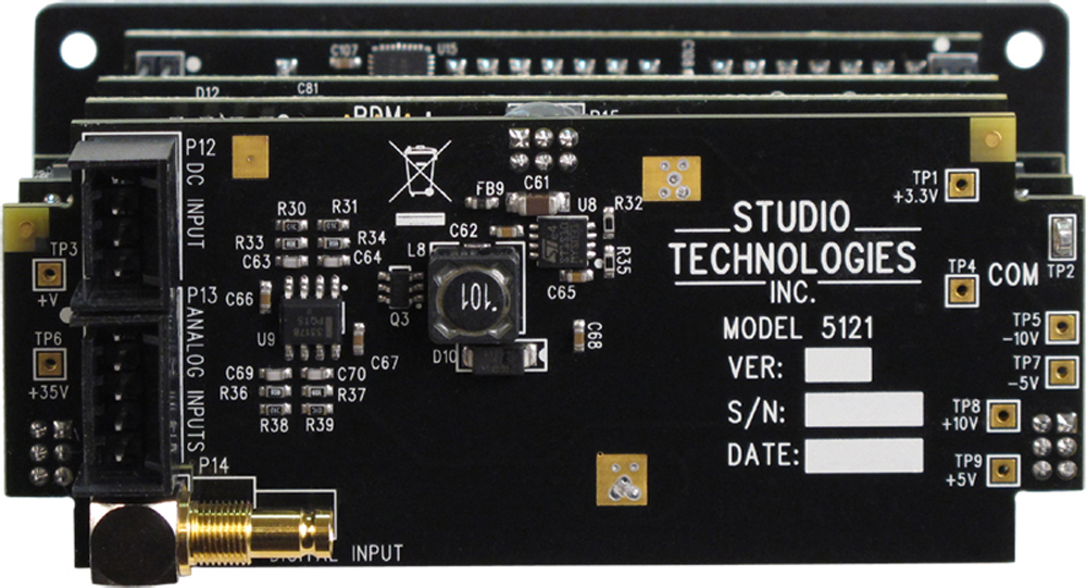
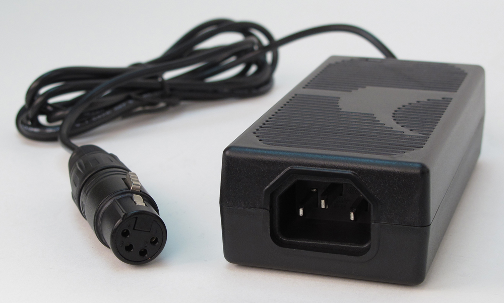
The Model 5121 requires an external source of nominal 12 volts DC for operation. The acceptable input voltage range is 10 to 18 allowing a variety of power sources to be utilized. Power supply circuitry within the Model 5121 creates the voltages required for the analog audio, digital audio, and IFB circuitry.
The Model 5121 uses standard connectors for fast, convenient interconnection. Line-level and IFB output connections are made using 3-pin male XLR connectors. The two analog audio inputs use a 5-position, 0.1-inch "header" connector. A DIN 1.0/2.3 coaxial connector is used to interface an AES3 unbalanced digital audio source. The DC power input and data bus connections use a 4-position, 0.1-inch header. Low-cost IDC (insulation displacement) mating connectors allow simple interconnection with the analog audio inputs and DC/data signals.
For compliance with international broadcast audio level standards two versions of the Model 5121 are available. The Model 5121S supports SMPTE® audio levels where the analog audio reference level is +4 dBu and the digital audio reference level is –20 dBFS (SMPTE RP155). The Model 5121E supports applications that require European Broadcast Union (EBU) compliance with an analog audio reference level of 0 dBu and a digital audio reference level of –18 dBFS (EBU R68).
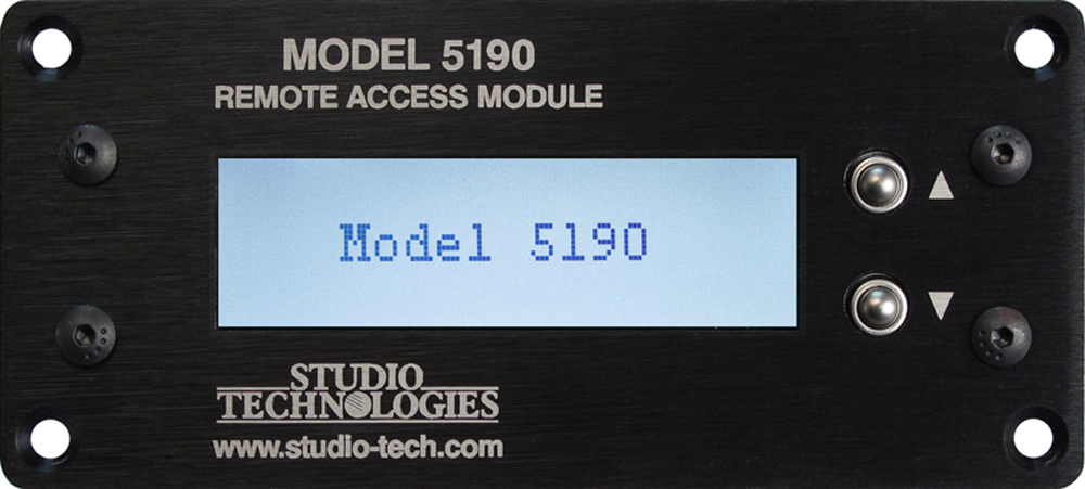
The Model 5121 is compatible with the Studio Technologies' Model 5190 Remote Access Module. This will allow monitoring and control, via an Ethernet connection, of several module operating and status parameters. A local RS-485 data bus allows up to 16 of the 5100-Series modules to be connected to a Model 5190. The status of the IFB DC output as well as the version number of the unit's firmware can be observed. The audio input source mode can be selected, with the choices being automatic, digital, or analog. In the automatic mode the digital input will have priority over the analog input. The gain of the input section can be adjusted with the supported range of ±12 dB in 3 dB steps.