The Model 214 is compatible with the latest broadcast and audio system environments that use the Dante technology. An Ethernet connection with Power-over-Ethernet (PoE) power is all that's required to make the unit part of a sophisticated, networked audio system. Connect a microphone and pair of headphones (or a broadcast headset) and the installation is complete. Whether it's the on-air audio, the talkback audio, or the headphone cue feed, superior audio quality is always maintained. A range of configuration choices allow the desired operating parameters to be easily selected. These choices can be made locally using pushbutton switches or remotely using the STcontroller application. And while flexible to configure, the user is presented with an easy-to-understand set of controls and indicators.
User Controls and Status Indicators
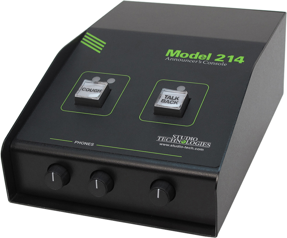
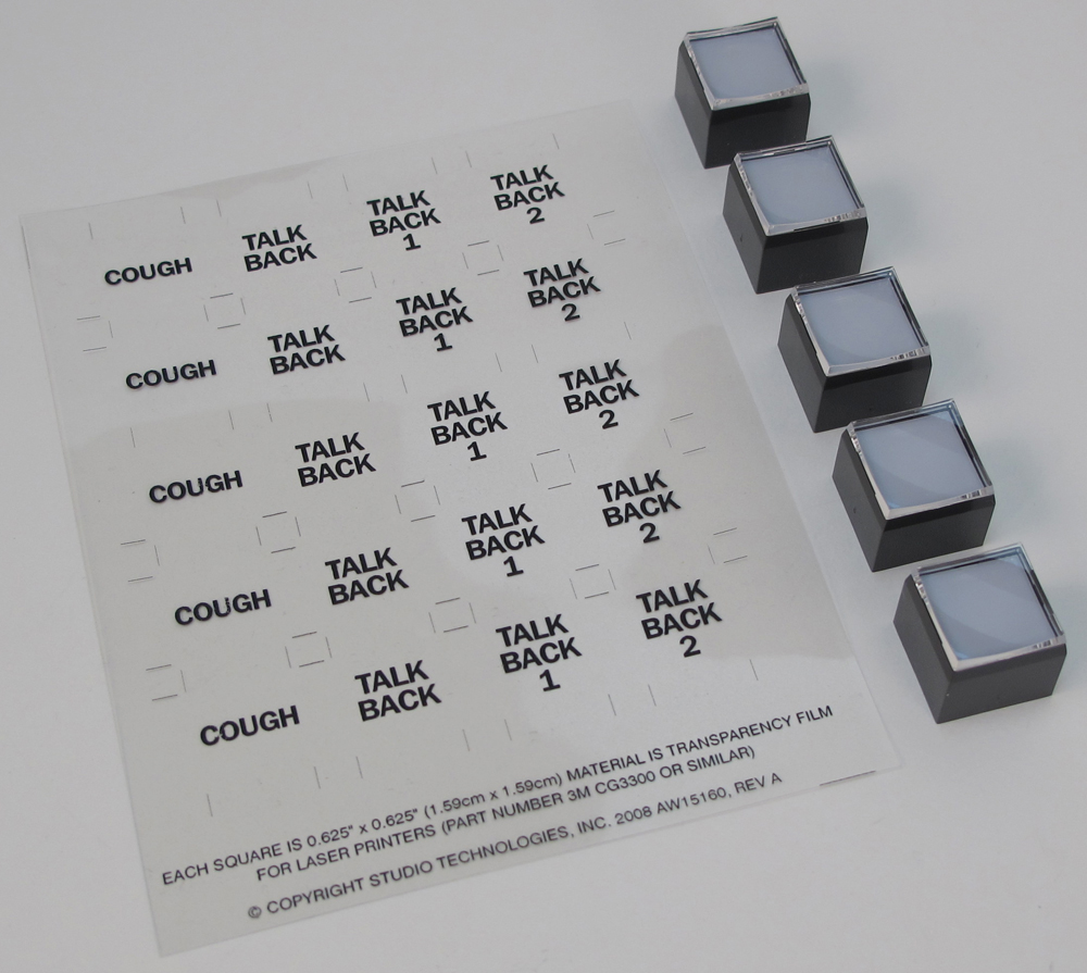
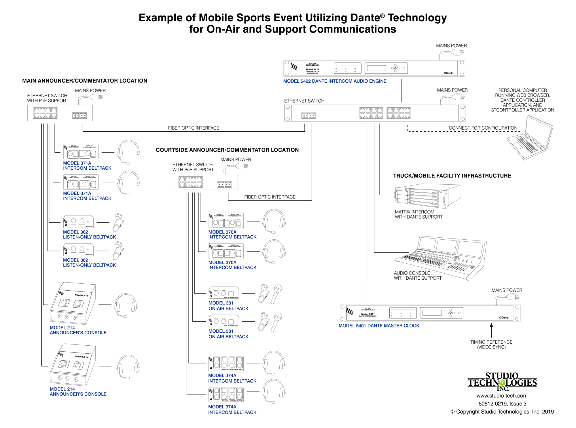
Two pushbutton switches, three LED indicators, and three rotary controls provide the user with a clear, easy-to-use interface. One pushbutton switch controls the status of the main output. This is the audio channel intended for on-air, announcement, or other primary uses. Two LEDs display the on/off status of the main output. A second pushbutton switch controls the status of the talkback output channel. This is the audio signal used to communicate with producers, directors, spotters, or other behind-the-scenes production personnel. A status LED is associated with the talkback pushbutton. The pushbutton switches use gold-plated contacts for reliable long-term operation and include backlighting using white LEDs. Three rotary controls allow the user to adjust the content and level of the headphone output.
Microphone Input
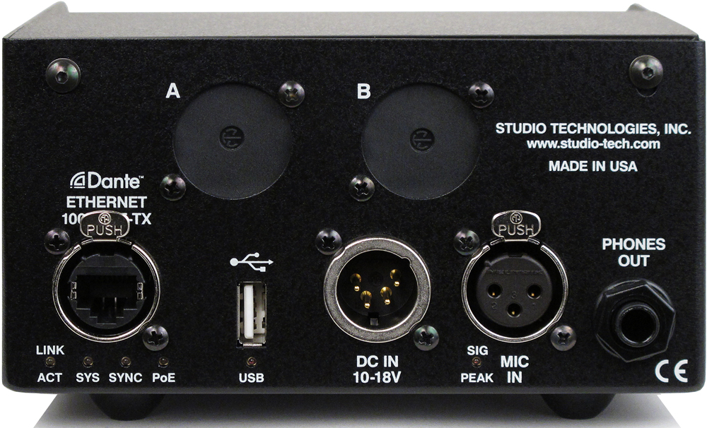
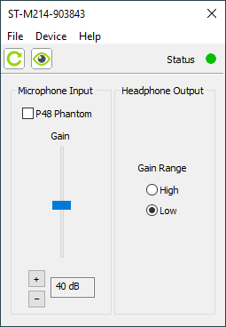
The Model 214 provides a high-performance microphone preamplifier which offers low-noise, low-distortion, and high headroom amplification over a 19 to 64 dB range. The gain is adjustable in 3-dB steps. A 2-digit display indicates the amplification in dB. The microphone input is compatible with balanced dynamic or condenser microphones. Phantom power is provided and meets the worldwide P48 standard. A dual-color LED indicator serves as an aid for optimizing the setting of the preamplifier's gain. Microphone signals are connected to the Model 214 by way of a standard 3-pin female XLR connector.
Microphone operating parameters can be set both locally and by way of the STcontroller remote control software application. Two pushbutton switches, accessible on the bottom of the unit, allow adjustment of the microphone preamplifier's gain and the on/off status of P48 phantom power. The STcontroller application allows personal computer users to both view and change the preamp gain and P48 on/off status.
Output Channels and their Operation
By way of the Dante interface, the Model 214 provides a main output channel and a talkback output channel. The main output channel is designed to serve as the on-air, stadium announcement, or other primary audio feed. The talkback output channel is intended to provide production trucks, control rooms, or support personnel with talent-originated cue signals.
In addition to the main and talkback output channels a tally tone/hot mic output channel is also provided. A configuration choice allows the output to be selected for either tally tone or hot mic operation. When selected for tally tone a 20 kHz sine-wave signal is present on the designated Dante transmitter (output) channel whenever the main output function is active. This tone can be useful as a "trigger" signal for other connected devices that need to provide an indication whenever the Model 214 is actively providing an "on air" audio signal. For example, a Studio Technologies' Model 391 Dante Alerting Unit can respond to the tally tone signal and provide an "on-air" indicator using its LED display. Alternatively, a Studio Technologies' Model 44D Interface unit could provide a contact closure whenever the tally tone output is active. When selected for hot mic signal operation an un-switched audio output whose source is the microphone preamplifier is provided on the Dante transmitter channel. This "always active" audio signal could be utilized in an application where the Model 214 is being used in conjunction with an intercom system or audio console. Production personnel may need to monitor the talent audio signal no matter the status of the main on/off and talkback functions.
A large part of the Model 214's unique power is the ability to configure the operation of the main and talkback functions. To meet the needs of the many specific broadcast and production applications, a variety of pushbutton operating modes are available. The main pushbutton can be selected to operate from among four modes. In the "push-to-mute" mode the pushbutton performs a momentary mute of the audio signal associated with the main output channel. In this way a "cough" pushbutton function is created, something typically required for television sports broadcasting. In the "push-to-talk" mode the pushbutton provides a momentary active function for the main output. This mode would be appropriate for an application such as stadium announcement. An alternate action "latching" configuration allows the pushbutton to enable or disable the audio signal associated with the main output channel as desired. This is useful in radio broadcasting, announce-booth, or voice-over applications. The fourth mode provides a hybrid function, supporting both push-to-talk and tap-to-enable/tap-to-disable operation. This operation is similar to that found in many broadcast intercom system user stations.
The pushbutton switch associated with the talkback function can be configured to operate from either of two modes. One of the modes supports a "push-to-talk" function. This is typically used for on-air broadcast applications. The other mode provides a hybrid function, the operation of which is discussed in the previous paragraph. The hybrid mode is especially useful when the Model 214 is used in a production-support application.
Overall Model 214 operation can be configured from among one on-air and two production modes. The Model 214's on-air mode is appropriate for on-air television, radio, and streaming broadcast applications. When on-air is selected the audio signal associated with the main output channel will always mute when the talkback function is active. This prevents audio that's intended for production or support personnel from being sent out the on-air audio path.
For non-on-air applications, the Model 214 can be configured to operate in either of two "production" modes. These allow the main output to be used as a second talkback output, rather than always muting when the talkback function is active. Using these production modes the unit can be even more powerful when used in a live event application, such as serving as a small "IFB" console for a sports-event spotter, musical director, or production assistant. In addition to changing how the main output functions, one of the production modes also supports using the headphone output for connection with amplified speakers. The headphone output level will automatically be reduced (attenuate or "dim") whenever the main or talkback output channels are active. This can enhance intelligibility and help prevent acoustical feedback from occurring between the speakers and the active microphone.
Headphone Output
The Model 214 provides a number of configuration choices that relate to the headphone output. These choices include the headphone output gain range, which audio sources are utilized, how the rotary level controls function, and what sidetone action will take place. Four headphone control source assignment modes are offered. These modes impact how the three rotary controls adjust the four Dante input channels and the sidetone audio signals.
The first two modes support standard on-air applications and use Dante audio input channels 1 and 2. In the broadcast world these two signals are often referred to as talent cue or IFB audio. In live television applications they typically originate in production trailers or control rooms and provide one channel of program-with-interrupt audio and a second channel with program-only audio. The third and fourth configuration modes allow all four of the Dante-provided audio sources to be utilized. These can be useful for more complex or specialized situations.
The three headphone level controls ("rotary pots") are provided for setting the "mix" of the selected audio input sources as well as adjusting the overall headphone output level. How these controls function depend on the selected headphone output mode. The first mode can be used to support traditional on-air sports applications. In this mode it would be typical to feed (connect) program-with-interrupt audio to the channel 1 audio input and program-only audio to the channel 4 audio input. Rotary control C1, located on the left side, is used to adjust the level of the program-with-interrupt audio signal that's routed to the left headphone output channel. Rotary control C2, located in the center, is used to adjust the level of the program-only audio signal that's routed to the right headphone output channel. For use with dual-channel or stereo cue signals, another headphone output mode provides a stereo ("level/balance") mode. In this mode rotary control C1 adjusts the level of both input channels 1 and 2, while rotary control C2 allows adjustment of the left/right level balance. In both of these modes rotary control C3, located on the right, is used to adjust the level of the side-tone audio signal that is sent to both the left and right headphone output channels.
In the third headphone output mode rotary control C1 adjusts the level of the channel 1 input audio source before it is routed to both the left and right headphone output channels. Rotary control C2 adjusts the level of the channel 2 audio source before it is routed to both the left and right headphone output channels. Rotary control C3 adjusts the level of both the channel 3 and channel 4 audio inputs which are then routed to, respectively, the left and right headphone output channels.
The fourth headphone output mode is similar to the third with the except that input 1 is routed only to the left headphone output channel while input 2 is routed only to the right headphone output channel. Inputs 3 and 4 will function in the same way in both modes 3 and 4.
The sidetone function allows audio from the Model 214's microphone preamplifier to be routed to the headphone output. This can be useful, providing the user with an aural confirmation of the signal connected to the mic input. It is especially important when a "mix-minus" talent cue signal is provided for the user. For application flexibility the sidetone function can be configured from among four choices, specifying when it will be active in relation to the status of the main and talkback functions.
To help minimize the chance of broadcast cues being missed, the action of the level controls can be configured so that there's always a minimum headphone output level. Alternately, the controls can be configured to fully mute when they are at their minimum (fully-counterclockwise) position. When the level control on the right side is used for sidetone it will always allow the sidetone signal to be fully muted.
The headphone output was designed to meet the needs of contemporary headphones and headsets. Specifically, the output circuits act as voltage drivers rather than power drivers. In this configuration they can provide high output levels with very low distortion and noise, along with minimal current consumption. The output circuits can safely drive stereo or mono loads. This ensures that all types of headphones, headsets, and earpieces can be directly connected.
A configuration feature allows the headphone output gain range to be selected. The low setting is appropriate for most applications where users need to listen at moderate levels. The high setting can be useful when monitoring at higher levels is warranted by an application.
Dante Audio-over-Ethernet
Audio data is sent to and from the Model 214 using the Dante audio-over-Ethernet media networking technology. For flexibility in meeting a variety of sonic requirements bit depths of up to 24 and sample rates of 44.1 and 48 kHz are supported.
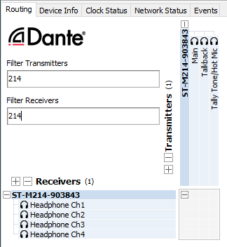
Audio transmitter (output) and receiver (input) channels on associated Dante-enabled devices can be assigned to the Model 214 using the Dante Controller software application. This makes selecting the way in which the Model 214 fits into an application a simple matter. For example, the main audio output channel can be assigned to the input of an audio console. The talkback audio output channel could be assigned to an input of a matrix intercom system. And the hot mic audio output channel could be routed directly to an amplified speaker for producer or director use. No special routing or "multing" using cables or patch points is required to send the output channels to multiple destinations. And a single mouse-click is all that's required to reroute the audio signals.
On the input side, the Model 214 allows up to four headphone cue sources to be received from an audio console, matrix intercom system, or a variety of other Dante-enabled devices; the sources don't need to originate from the same device. "Program" audio could be supplied by an audio console while "IFB" (interrupted foldback or talent cue) audio could be supplied by a matrix intercom system.
Ethernet Data, PoE, and DC Power Source
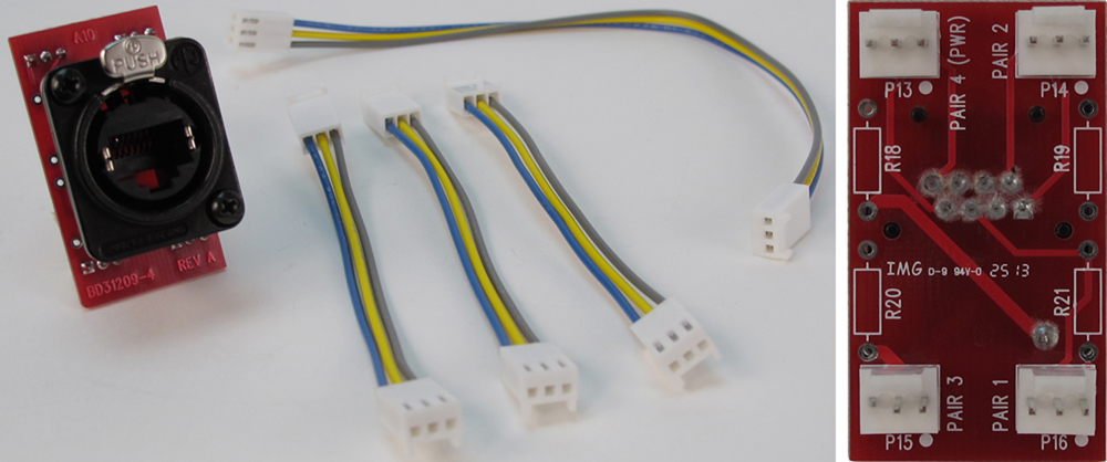
The Model 214 connects to a data network using a standard 100 Mb/s twisted-pair Ethernet interface. The physical interconnection is made by way of a Neutrik® etherCON RJ45 connector. While compatible with standard RJ45 plugs, etherCON allows a ruggedized and locking interconnection for harsh or high-reliability environments. The Model 214's operating power can be provided by way of the Ethernet interface using the Power-over-Ethernet (PoE) standard. This allows fast and efficient interconnection with the associated data network. To support PoE power management, the Model 214's PoE interface reports to the power sourcing equipment (PSE) that it's a class 2 (low power) device. The unit can also be powered using an external source of 12 Vdc. For redundancy, both power sources can be connected simultaneously. If both sources are connected PoE will power the unit. Four LEDs display the status of the network connection, PoE power source, and Dante interface.
Configuration and Flexibility
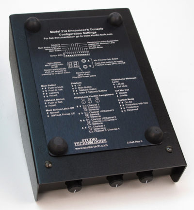
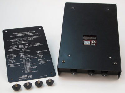
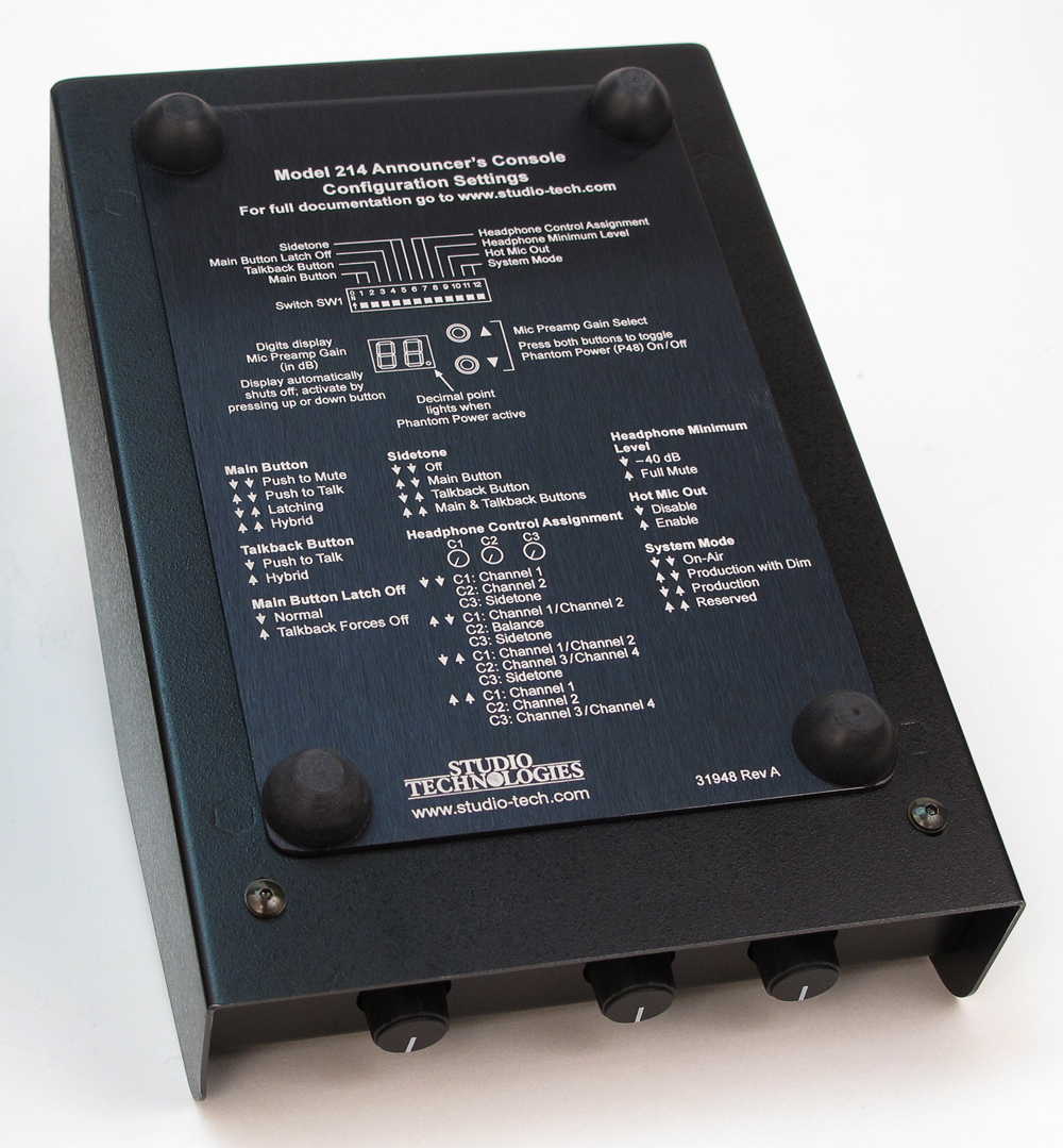
Model 214 configuration settings can be made using twelve DIP switches and two pushbutton switches. The STcontroller software application can be used to view and change the gain of the microphone preamplifier, the on/off status of P48 phantom power, and the headphone output gain range. The 12-position switch array configures parameters such as the pushbutton operating modes, headphone operating mode, sidetone function, and the overall system mode. The pushbuttons can be used to set the gain of the microphone preamplifier, control the on/off status of the microphone P48 phantom power function, and select the headphone output gain range. The switches and pushbuttons are accessible via the bottom of the Model 214's enclosure; the unit does not have to be disassembled. Changes made to any of the configuration parameters become active immediately. To prevent unwanted access to the configuration switches and pushbuttons a security plate, included with each unit, is attached to the bottom of the enclosure.
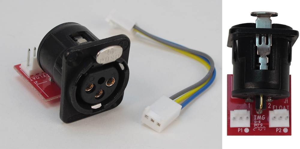
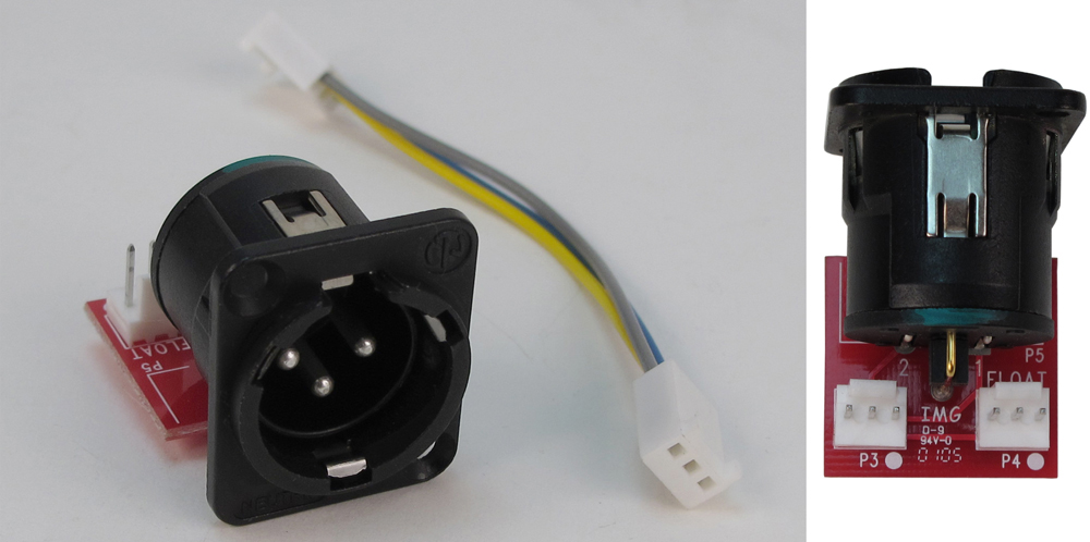
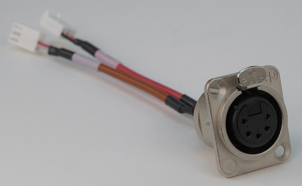
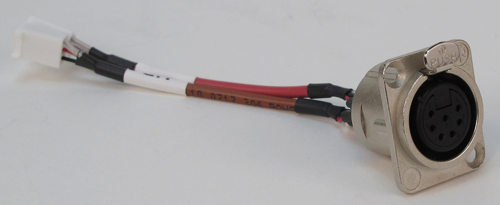
In the world of broadcast and production audio it's fair to say that applications vary widely. To this end, one or two additional XLR connectors can easily be mounted into the Model 214's back panel. Multiple 3-position "headers" located on the Model 214's circuit board provide technician access to many of the input and output connections. Using a variety of optional factory-supplied modules and interface cable kits allows a Model 214 to be optimized to meet the needs of specific applications. For example, some applications may prefer to use a multi-pin XLR connector to interface with a headset. This can easily be accomplished by installing the appropriate 6- or 7-pin XLR connector kit and making a few simple connections. Other applications may benefit from having "mult" or "loop-through" connections, something easily incorporated into a Model 214. And access to the relay contacts can be made adding a 4-pin XLR connector kit.
Two general-purpose relay contacts are provided on the Model 214's circuit board. Accessible using 3-pin "header" connectors they allow specialized configurations to be created. Under software control, the form-A (normally open) solid-state relay contacts follow the state of the main and talkback pushbuttons. Taking advantage of the two locations provided for additional XLR connectors, a technician may easily implement a variety of functions such as a tally indication or audio muting during talkback.
Firmware Updating
A USB connector, located on the Model 214's back panel, allows the operating firmware (embedded software) to be updated using a standard USB flash drive. The Model 214 uses Audinate's Ultimo™ integrated circuit for implementing Dante. The integrated circuit's firmware can be updated via the Ethernet connection, helping ensure that its capabilities remain up to date.


