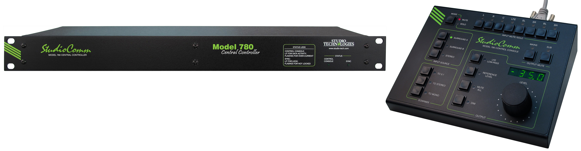
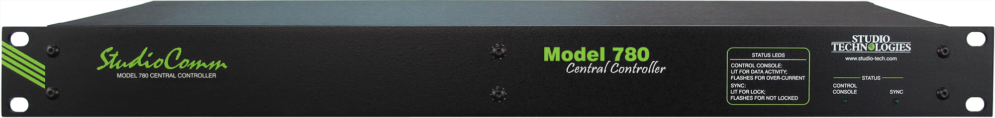
Model 780-03 Central Controller
General Audio:
Supported Sample Rates: 44.1, 48, 88.2, and 96 kHz
Word Length: 24 bits maximum
Internal Processing: 32 bits
Input-to-Output Latency: two samples (e.g., 0.042 milliseconds @ 48 kHz sample rate)
Digital Audio Inputs: 3 (18 audio channels total)
Configuration: two surround (7.1) and one stereo
Type: balanced AES3 (110 ohms, 5 Vpp)
Connector—Surround Inputs: 25-pin female D-subminiature (DB-25F), AES59-2012 compliant
Connector—Stereo Input: 3-pin female XLR
Sample Rate Conversion (SRC):
Application: available on the stereo input
Input Sample Rate Range: 8 to 216 kHz, limited to 1/6 to 6 times the output sample rate
Latency: 1 millisecond, nominal
LFE Input Channel Low-Pass Filter: –6 dB @ 120 Hz, 48 dB-per-octave, on/off selectable
Sync Source: configured to follow L/R of currently selected input or signal connected to sync input
Sync Input:
Compatible Sources: word clock, DARS (AES11), bi-level video, tri-level video
Jitter: 4 ns pp maximum
Connector: BNC (per IEC 60169-8 Amendment 2)
Termination: 75 ohms, selectable on/off
Digital Monitor Outputs: 16 channels (8 pairs)
Configuration: organized as two surround (7.1), one pre-fader, and one post-fader
Dynamic Range: >135 dB
Type: balanced AES3 (110 ohms, 5 Vpp)
Connector: 25-pin female D-subminiature (DB-25F), AES59-2012-compliant
Analog Monitor Outputs: 8
Configuration: organized as one surround (7.1), post-fader
Type: electronically balanced, source impedance 200 ohms
Nominal Level: +4 dBu @ –20 dBFS input source and level control at maximum setting
Maximum Level: +24 dBu into 2000 (2 k) ohms or greater
Frequency Response, Digital Inputs to Analog Monitor Outputs: 10 Hz-20 kHz +0.0/–0.3 dB @ 48 kHz sample rate; –3 dB @ 64 kHz
Distortion (THD+N): <0.002%, –1 dBFS, 20-22 kHz, 22 kHz bandwidth
Dynamic Range: >116 dB
Crosstalk: –98 dB at 1 kHz; –97 dB at 16 kHz, ref –1 dBFS input
Connector: 25-pin female D-subminiature (DB-25F), AES59-2012-compliant
Configurable Input Delay: 0 to 340 milliseconds @ 48 kHz sample rate (scales up or down depending on actual sample rate)
Post-Fader Monitor Output Level Offsets: each surround (7.1) channel independently adjustable in 0.5-dB steps over a ±12-dB range. (Digital and analog outputs associated with a specific channel share the same setting.)
Bass Management:
Crossover Frequency and Type: –6 dB @ 40, 50, 60, or 80 Hz, symmetrical for low-pass and high-pass filters, maximally flat
Filter Slope: 12 dB-per-octave or 24 dB-per-octave
Overall Operation: on/off selectable
Downmix Functions: To 5.1, To Stereo, and To Mono
Control Console Interface:
Type: RS-485, 115.2 kbit/s, 8-1-N
Polling Interval: 80 milliseconds, nominal
Power: 12 Vdc, 500 mA maximum
Connector: 9-pin female D-subminiature (DE-9F)
Remote Control Inputs: 2
Functions: remote mute all, remote dim
Type: 3.3 Vdc logic, activates on closure to system common
Connector: 9-pin female D-subminiature (DE-9F)
AC Mains:
Requirement: 100 to 240 V, +10/–15%, 50/60 Hz, 15 W maximum
Connector: 3-blade, IEC 320 C14-compatible (mates with IEC 320 C13)
Dimensions:
19.00 inches wide (48.3 cm)
1.72 inches high (4.4 cm)
7.00 inches deep (17.8 cm)
Mounting: one space (1U) in a standard 19-inch rack
Weight: 3.6 pounds (1.6 kg)
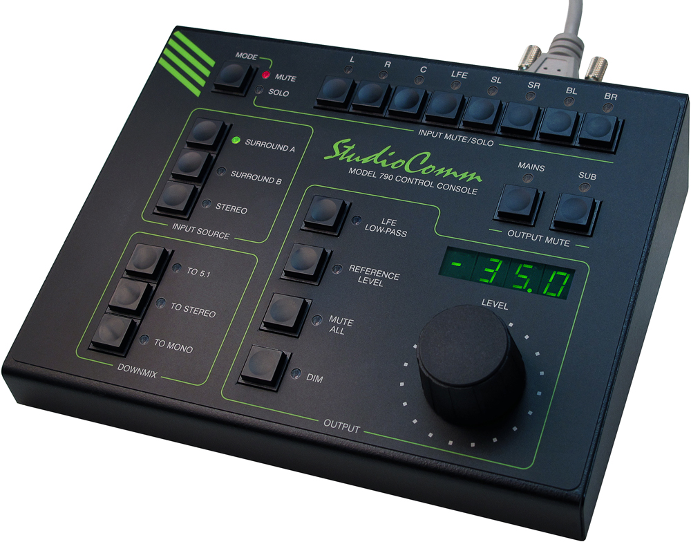
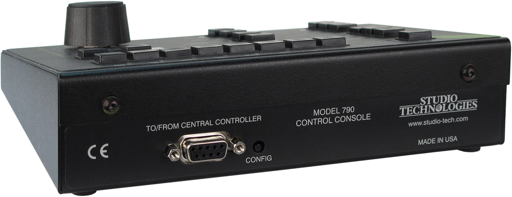
Model 790 Control Console
Application: up to four Model 790 Control Consoles can be connected to a Model 780-03 Central Controller
Power: 12 Vdc nominal (9 Vdc minimum), maximum current 100 mA, provided by Model 780-03 Central Controller
Control Data:
Type: RS-485
Data Rate/Format: 115.2 kbit/s, 8-N-1
Connector: 9-pin female D-subminiature (DE-9F)
Dimensions (Overall):
7.20 inches wide (18.3 cm)
2.20 inches high (5.6 cm)
5.40 inches deep (13.7 cm)
Weight: 1.7 pounds (0.8 kg)
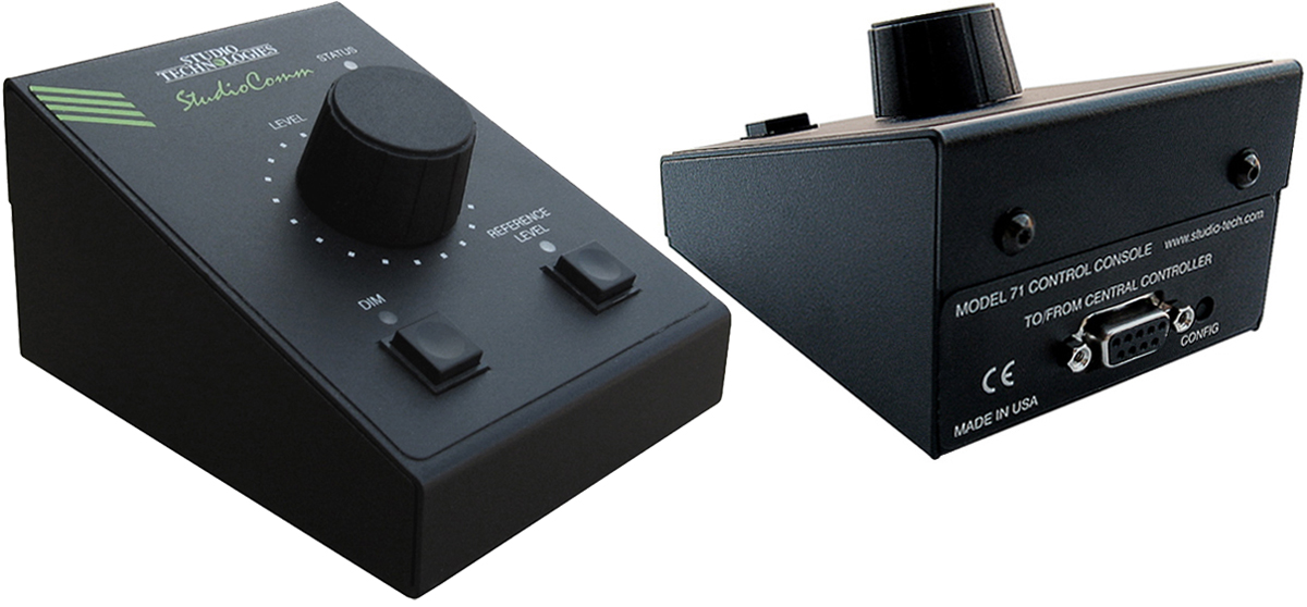
Model 71 Control Console
Application: up to three Model 71 Control Consoles can be connected to a Model 780-03 Central Controller
Power: 12 Vdc nominal (9 Vdc minimum), maximum current 35 mA, provided by Model 780-03 Central Controller
Control Data:
Type: RS-485
Data Rate/Format: 115.2 kbit/s, 8-N-1
Connector: 9-pin female D-subminiature (DE-9F)
Dimensions (Overall):
3.20 inches wide (8.1 cm)
2.20 inches high (5.6 cm)
4.10 inches deep (10.4 cm)
Weight: 0.8 pounds (0.4 kg)
Specifications subject to change without notice.