Announcements
[hsas-shortcode speed="30" direction="left" gap="120"]

Model 780-03 Central Controller and Model 790 Control Console

Order Code: Discontinued

The Model 780-03 Central Controller and Model 790 Control Console have been factory discontinued. For documentation please refer to the Reference Archive for Discontinued Products page.

Click to expand and read more...

Documentation

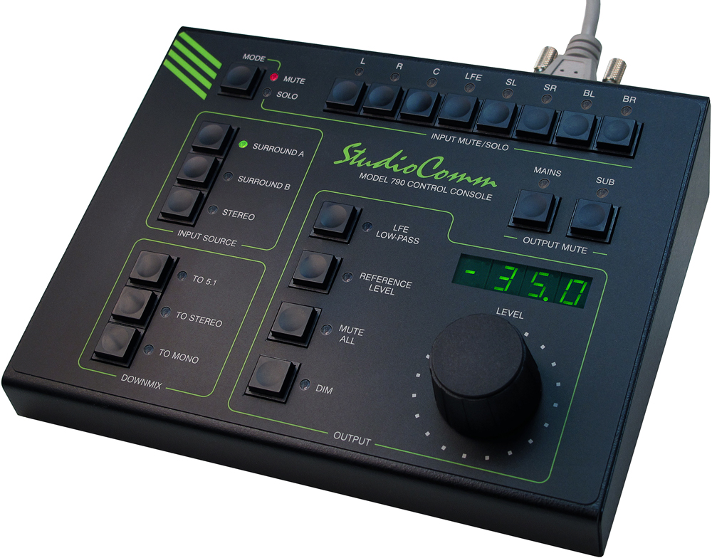
A StudioComm for Surround system starts with the Model 790 Control Console. It's the system's "command center" and is designed to reside at a user's location, allowing fingertip selection of all monitoring functions. Numerous LEDs provide complete status information. A 4-digit numeric display indicates the level of the post-fader digital and analog monitor outputs. A major strength of the Model 790 is its ability to configure, under software control, many important operating parameters. Intended for secondary monitoring locations that don't require all of the Model 790's features, the Model 71 Control Console is a compact user control surface. It provides three of the most basic functions: a rotary level control, dim on/off button, and reference level on/off button.

Most installations will use only one Model 790 Control Console. However, up to three additional Model 790 or Model 71 Control Consoles can also be connected. This provides multiple users with control over a facility's monitor system. And to make installation simple, the Model 780-03 provides power for all connected Model 790 or Model 71 units.

The core of this StudioComm for Surround system is the Model 780-03 Central Controller. The one-rack-space unit contains circuitry that supports balanced digital audio inputs, balanced digital and analog monitor outputs, digital audio and control processing, and interfacing for the user control surface(s). The Model 780-03 provides two surround (7.1) and one stereo digital audio inputs. These balanced digital inputs are AES3-compliant; sources of this type are ubiquitous in many post-production and audio facility environments. The inputs allow a sample rate of 44.1, 48, 88.2 or 96 kHz and a bit depth of up to 24 to be supported. Circuitry associated with the stereo input provides sample rate conversion (SRC) capability, allowing a wide range of digital audio sources to be monitored. To compensate with processing delays (latency) associated with associated video displays up to 340 milliseconds of input delay can be selected. For flexibility, two delay values can be configured, allowing real-time selection as desired. A number of different signals can serve as the Model 780-03's digital audio timing reference. For synchronization with a master timing reference a dedicated source of word clock, DARS (AES11), bi-level video, or tri-level video can be connected. Alternately, the L/R connection of the actively selected surround or stereo input source can serve as the timing reference.

A range of digital and analog surround (7.1) monitor outputs are provided. The post-fader digital and analog monitor outputs are intended for connection to monitor loudspeaker systems. The pre-fader digital monitor output can be used with metering systems that require signals that aren't impacted by level control or other monitoring functions. The digital monitor outputs are compatible with equipment that requires balanced AES3 digital audio signals with an output impedance of 110 ohms and a signal level of 5 volts peak-to-peak (Vpp).

A sophisticated bass management function is integral to the Model 780-03's design and can be enabled if desired. It can apply to both the post-fader digital and analog monitor output channels. The overall goal of bass management is very simple: ensure that the entire audio bandwidth of all channels can be accurately monitored. Many loudspeaker systems have inherent low-frequency limitations, preventing a true sonic "picture" of the source material from being presented. To overcome this, the low-frequency energy from the seven channels associated with the surround inputs and the two channels associated with the stereo input can be separated and routed to the subwoofer (SUB) channel of the monitor outputs. Several of the bass management functions can be configured to match the requirements of specific installations.

Great care was taken in designing the system's architecture, ensuring that the character of the audio input signals was preserved. All audio processing, including bass management, is performed in 32-bit logic using a high-speed field-programmable gate array (FPGA) integrated circuit. High-performance integrated circuits are used to perform input, output, and clocking tasks.

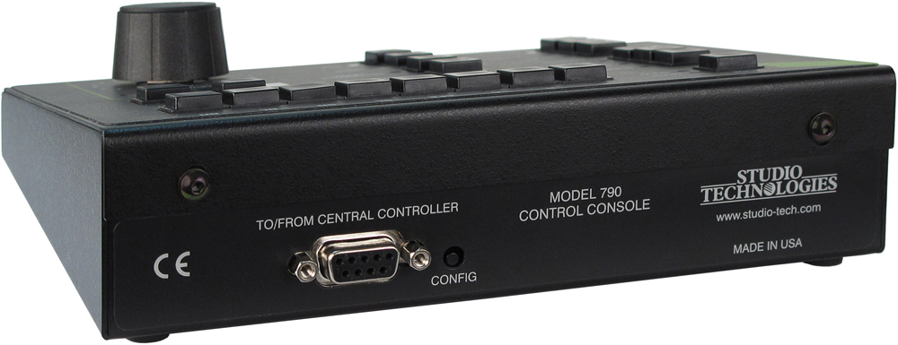
The Model 780-03 occupies one space (1U) in a standard 19-inch rack. Digital audio sources are interfaced with the Model 780-03 using one 25-pin female D-subminiature connector and one 3-pin female XLR connector. A BNC connector is used to interface with an external sync source. Digital and analog monitor output signal connections are made using two 25-pin female D-subminiature connector. One 9-pin female D-subminiature connector is used to connect the Model 780-03 with a maximum of four Model 790 or Model 71 Control Consoles. A second 9-pin "D-sub" connector is used to interface with remote control signals. AC mains power is connected directly to the Model 780-03, with an acceptable range of 100 to 240 V, 50/60 Hz.

Additional Details

The Model 790 provides three buttons and associated LEDs for selection of the source to be monitored. The choices are the two surround inputs and the stereo input; only one source can be monitored at a time. It's interesting to note that while the surround inputs have an LFE channel associated with them, the corresponding post-fader digital and analog monitor output channels are designated as subwoofer (SUB), rather than LFE. This terminology was selected to highlight the fact that this output channel may include more than just LFE content. The bass management function, if enabled, will redirect low-frequency energy from the main channels, combine it with the contents from the LFE input channel, and route the combination to the subwoofer (SUB) channels of the post-fader digital and analog monitor outputs.

An LFE low-pass filter function is provided as a means of checking the audio content in the LFE channel of a selected surround input. The user can enable and disable the function as required, helping to ensure that the proper signals are being mixed to the LFE channel. Having the correct audio content in the LFE channel can be critical as the LFE channel is typically band-restricted during distribution.

The post-fader digital and analog monitor output levels can be controlled by way of a large, easy-to-use rotary control. The control, actually a digital encoder, allows level selection in precise 0.5-dB steps. The auto mute all function causes the post-fader digital and analog monitor output channels to automatically mute whenever the output level control reaches maximum attenuation. Using the reference level function, the post-fader digital and analog monitor output levels can be set to a pre-configured value. This is provided for audio-with-picture applications that require a specific monitor output level. The reference level is easily configured by taking an electronic "snapshot" of the desired monitor output level. For user confirmation, the 4-digit LED display will show the level of the post-fader digital and analog monitor output channels. To match the needs of a facility, the display can be configured to show either the attenuation level or the sound pressure level (SPL).

The dim function allows the post-fader digital and analog monitor output levels to be reduced by a fixed dB amount. The dim level is configured from among four available values. A mute all function allows the post-fader digital and analog monitor output channels to be simultaneously muted. The input mute/solo section allows an input channel to be muted or monitored as desired. Multiple channels can also be simultaneously selected for muting or "soloing."

Two output mute functions are also provided. One button allows the seven main channels of the post-fader digital and analog monitor outputs to be muted. A second button allows the subwoofer (SUB) channels of the post-fader digital and analog monitor outputs to be muted. The output mute functions, along with the input mute/solo function, allow a user complete flexibility when checking an input source and its path to the loudspeaker system(s). These mute and solo resources are crucial in a multichannel environment, especially when signals are passing through the bass management function.

Three downmix functions allow the selected input source to be checked for compatibility with common audio channel formats. This can help ensure that surround and stereo mixes correctly "fold down" into formats that utilize less channels than the original. Errors can be quickly identified and then corrected. The downmix functions, To 5.1 and To Stereo, apply only to the two surround (7.1) sources. The To Mono downmix function applies to the surround and stereo inputs. Several of the downmix parameters can be configured to best meet the needs of an application. The downmix functions always impact the post-fader digital and analog monitor outputs. A configuration setting allows the pre-fader digital monitor output to be selected for pre- or post-downmix operation.

For flexibility, the StudioComm for Surround system is designed to easily integrate with equipment such as production intercom systems, on-air or recording tally signals, and audio consoles. Two remote-control inputs provide access to the mute all and dim functions. By providing access to these functions, talkback or slate activity from an audio console or other communications system can control the level of the post-fader digital and analog monitor outputs.

Model 780-03 Central Controller

General Audio:
Supported Sample Rates: 44.1, 48, 88.2, and 96 kHz
Word Length: 24 bits maximum
Internal Processing: 32 bits
Input-to-Output Latency: two samples (e.g., 0.042 milliseconds @ 48 kHz sample rate)

Digital Audio Inputs: 3 (18 audio channels total)
Configuration: two surround (7.1) and one stereo
Type: balanced AES3 (110 ohms, 5 Vpp)
Connector—Surround Inputs: 25-pin female D-subminiature (DB-25F), AES59-2012 compliant
Connector—Stereo Input: 3-pin female XLR

Sample Rate Conversion (SRC):
Application: available on the stereo input
Input Sample Rate Range: 8 to 216 kHz, limited to 1/6 to 6 times the output sample rate
Latency: 1 millisecond, nominal

LFE Input Channel Low-Pass Filter: –6 dB @ 120 Hz, 48 dB-per-octave, on/off selectable

Sync Source: configured to follow L/R of currently selected input or signal connected to sync input

Sync Input:
Compatible Sources: word clock, DARS (AES11), bi-level video, tri-level video
Jitter: 4 ns pp maximum
Connector: BNC (per IEC 60169-8 Amendment 2)
Termination: 75 ohms, selectable on/off

Digital Monitor Outputs: 16 channels (8 pairs)
Configuration: organized as two surround (7.1), one pre-fader, and one post-fader
Dynamic Range: >135 dB
Type: balanced AES3 (110 ohms, 5 Vpp)
Connector: 25-pin female D-subminiature (DB-25F), AES59-2012-compliant

Analog Monitor Outputs: 8
Configuration: organized as one surround (7.1), post-fader
Type: electronically balanced, source impedance 200 ohms
Nominal Level: +4 dBu @ –20 dBFS input source and level control at maximum setting
Maximum Level: +24 dBu into 2000 (2 k) ohms or greater
Frequency Response, Digital Inputs to Analog Monitor Outputs: 10 Hz-20 kHz +0.0/–0.3 dB @ 48 kHz sample rate; –3 dB @ 64 kHz
Distortion (THD+N): <0.002%, –1 dBFS, 20-22 kHz, 22 kHz bandwidth
Dynamic Range: >116 dB
Crosstalk: –98 dB at 1 kHz; –97 dB at 16 kHz, ref –1 dBFS input
Connector: 25-pin female D-subminiature (DB-25F), AES59-2012-compliant

Configurable Input Delay: 0 to 340 milliseconds @ 48 kHz sample rate (scales up or down depending on actual sample rate)

Post-Fader Monitor Output Level Offsets: each surround (7.1) channel independently adjustable in 0.5-dB steps over a ±12-dB range. (Digital and analog outputs associated with a specific channel share the same setting.)

Bass Management:
Crossover Frequency and Type: –6 dB @ 40, 50, 60, or 80 Hz, symmetrical for low-pass and high-pass filters, maximally flat
Filter Slope: 12 dB-per-octave or 24 dB-per-octave
Overall Operation: on/off selectable

Downmix Functions: To 5.1, To Stereo, and To Mono

Control Console Interface:
Type: RS-485, 115.2 kbit/s, 8-1-N
Polling Interval: 80 milliseconds, nominal
Power: 12 Vdc, 500 mA maximum
Connector: 9-pin female D-subminiature (DE-9F)

Remote Control Inputs: 2
Functions: remote mute all, remote dim
Type: 3.3 Vdc logic, activates on closure to system common
Connector: 9-pin female D-subminiature (DE-9F)

AC Mains:
Requirement: 100 to 240 V, +10/–15%, 50/60 Hz, 15 W maximum
Connector: 3-blade, IEC 320 C14-compatible (mates with IEC 320 C13)

Dimensions:
19.00 inches wide (48.3 cm)
1.72 inches high (4.4 cm)
7.00 inches deep (17.8 cm)

Mounting: one space (1U) in a standard 19-inch rack

Weight: 3.6 pounds (1.6 kg)


Model 790 Control Console

Application: up to four Model 790 Control Consoles can be connected to a Model 780-03 Central Controller

Power: 12 Vdc nominal (9 Vdc minimum), maximum current 100 mA, provided by Model 780-03 Central Controller

Control Data:
Type: RS-485
Data Rate/Format: 115.2 kbit/s, 8-N-1
Connector: 9-pin female D-subminiature (DE-9F)

Dimensions (Overall):
7.20 inches wide (18.3 cm)
2.20 inches high (5.6 cm)
5.40 inches deep (13.7 cm)

Weight: 1.7 pounds (0.8 kg)


Model 71 Control Console

Application: up to three Model 71 Control Consoles can be connected to a Model 780-03 Central Controller

Power: 12 Vdc nominal (9 Vdc minimum), maximum current 35 mA, provided by Model 780-03 Central Controller

Control Data:
Type: RS-485
Data Rate/Format: 115.2 kbit/s, 8-N-1
Connector: 9-pin female D-subminiature (DE-9F)

Dimensions (Overall):
3.20 inches wide (8.1 cm)
2.20 inches high (5.6 cm)
4.10 inches deep (10.4 cm)

Weight: 0.8 pounds (0.4 kg)

Specifications subject to change without notice.

Documentation

Data Sheet  

Title
StudioComm Model 780-03 Central Controller / Model 790 Control Console Data Sheet
Description
Issue 2
Release Date
05-Mar-2020

User Guide  

Title
StudioComm Model 780-03 Central Controller / Model 790 Control Console User Guide
Description
Issue 4
S/N Range
M780-03: 00151-later; M790: 00151-later
Firmware
M780-03: Software 1.00-higher, FPGA 4.15-higher; M790: Software 1.00-higher
Release Date
24-Dec-2020

Images  

Model 780 Central Controller Front View
Model 780-03 Central Controller Rear View
Model 790 Control Console Top Angle View
Model 790 Control Console Rear Angle View
Skip to content
Menu