The Model 742A is targeted for use by operators with numerous audio sources that need to be quickly and reliably adjusted and routed to create one or two independent audio mixes. In these days of operators having too many tasks to handle, and too little time to do them, the Model 742A is a refreshing combination of performance and simplicity. Using their experience in mobile broadcast applications, the engineers at Studio Technologies were able to design the Model 742A to include all the crucial features required to meet the needs of fast-paced news-gathering operations, while still providing the operator with an easy-to-use product.
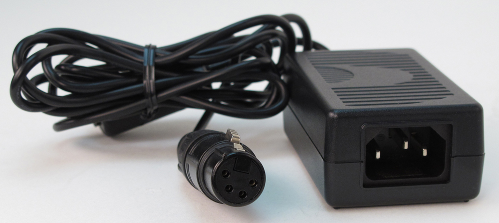
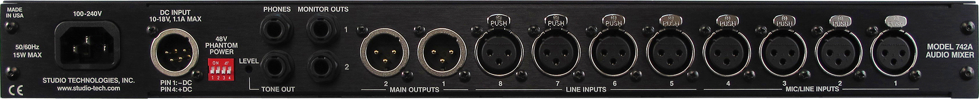
The hallmarks of the Model 742A are application flexibility, simplicity in use, audio quality, and long-term reliability. For powering, the unit can be directly connected to an AC mains source. A true "universal input" design that's intended for worldwide use, the input voltage can range from 100 to 240 volts, 50/60 Hz. A source of 10 to 18 volts DC can also be connected to power the Model 742A. If both AC and DC sources are connected, the AC source will power the unit while the DC source will serve as a backup. In this way a battery can be connected, ready to serve in a standby capacity.
A carefully selected feature set ensures that the Model 742A will be a "team player" when it is integrated into an audio system. A number of internal configuration "jumpers" allow the unit's performance to be tailored to the needs of specific installations. And while there's flexibility on the inside, the operator is presented with an easy-to-use set of front-panel controls and indicators—the operator typically never has to access the back panel to operate the unit. In this way the goal of delivering successful on-air and production audio, day-after-day, can best be achieved. The Model 742A's audio quality is "pro" throughout. The components were carefully selected to deliver low-noise, low-distortion performance.
Long-term reliability was also part of the Model 742A's design criteria. To that end the unit's enclosure is made of lightweight yet rugged aluminum with a steel front panel for overall rigidity which adds to rack-mounting stability. On the inside, a conservative circuit design combines state-of-the-art integrated circuits for sonic quality with numerous filtering and protection components for long-term reliability.
Mic/Line Inputs
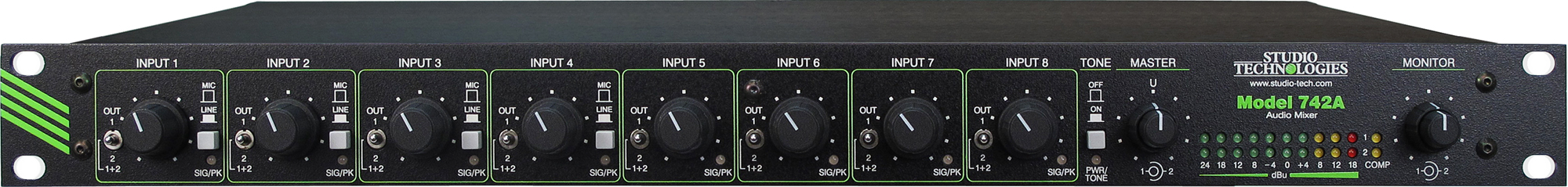
Four input channels are provided for connection to microphone or line-level signals. The electronically balanced circuitry is "ruggedized" for reliable operation under tough operating conditions. The low-noise, low-distortion, high-headroom audio performance is what's expected of sophisticated "pro audio" equipment. Features provided for each input channel include an input sensitivity button, rotary level control, signal level status LED, and output bus assignment switch. To support condenser microphones, the four mic/line inputs can be individually configured to supply 48 volt phantom power. Four DIP switches, accessible on the back panel, allow individual channel phantom power on/off control.
For ease of use, each input's rotary level control sets the gain of the input circuit as well as the level being sent to the selected main output bus (or buses). For convenience the input sensitivity button, as with the other Model 742A operator controls, is located on the front panel. For operator assistance, a dual-color level status LED provides signal present and peak level indication.
Associated with each mic/line input channel is a 3-position output bus assignment switch. This allows each input to be assigned to bus 1, bus 2, or both, quickly creating two fully independent audio "feeds." Bus assignment switches, rather than the more-typical "pan pots," were specifically selected for the Model 742A's design. This allows a more positive assignment of an input source to the desired output bus (or buses), minimizing the chance of unwanted "leakage." Pan pots are fine in an audio mixer destined for use in stereo music situations, but are inferior when used for two-bus applications.
Line Inputs
Four input channels are provided for connection to line-level signals. Features provided for each line input channel include a rotary level control, level status LED, and output bus assignment switch. The rotary level control is used to set the amount of input signal that is sent to the selected main output bus (or buses). The dual-color level status LED provides signal present and peak level indication. A 3-position switch allows the input signal to be assigned to the desired output bus (or buses).
Main Output Buses
Signals from the eight input channels (four mic/line and four line) are routed and combined to create the two main output buses. A dual rotary control is used to independently set the overall level of the two buses. An electronically balanced output circuit is associated with each main output bus. They provide line-level signals capable of driving balanced or unbalanced loads of 600 ohms or greater. Separate studio-quality audio compressor circuits are provided to control the dynamic range of each main output bus. An LED indicator is associated with each compressor, lighting whenever the circuit is actively controlling signal level. Far from simple "clippers," the compressor circuits utilize sophisticated laser-trimmed voltage-controlled amplifier (VCA) integrated circuits for quiet, low-distortion operation. To help minimize operator error no compressor on/off switches are provided on the Model 742A's front panel. Internal configuration jumpers determine the compressor circuits' operating modes. From the factory the jumpers are set so that the compressors' operating threshold is 6 dB above the nominal +4 dBu output level. This is an excellent general-purpose setting for broadcast use where voice signals are the primary audio content.
To meet the needs of other applications, a technician can change the jumpers to make the compressor threshold 2 dB above the nominal +4 dBu. This could prove useful when using the Model 742A with level-sensitive RF transmission systems. For other applications a technician can set the jumpers to a third position which completely disables the compressor functions.
Monitor Section
The Model 742A's monitor section provides two line-level monitor outputs and a "stereo" headphone output. Monitor outputs 1 and 2 are electrically balanced with their input sources associated with output buses 1 and 2, respectively. The headphone output has main output bus 1 as its left-channel source and main output bus 2 as its right-channel source. Associated with the monitor section is a dual rotary level control that allows independent setting of the monitor output levels. The level of the headphone output is always adjusted using these controls. Internal configuration jumpers are used to select the exact signal sources for the line-level monitor outputs. They can either be "post" the controls, allowing an adjustable output level, or set to a fixed –10 or +4 dBu nominal level. This allows the monitor outputs to be compatible with a variety of monitor amplifiers, amplified loudspeakers, or even to serve as an additional set of main bus line-level outputs.
From the factory the Model 742A's monitor outputs are configured to the "post" setting, enabling them to "follow" the setting of the front-panel level controls. This is appropriate where monitor loudspeakers and associated power amplifier channels are used. A technician can change the jumper positions so that the monitor outputs are electrically before ("pre") the level controls. Two jumper positions are available, corresponding to –10 and +4 dBu nominal output levels. The –10 position can be very useful when connecting the monitor outputs to amplified loudspeakers that contain user-accessible level controls. Examples of amplified speakers that contain user level controls include the popular Fostex® 6301-series. With the jumpers set to the –10 position, only one level control—the one in the amplified speaker—would be used to set that speaker's level. This can greatly minimize operator confusion and enhance performance.
When the unit is configured for +4 operation the monitor outputs are again "pre" the level controls, but this time with a nominal level of +4 dBu. This can be used for various applications, including providing an additional set of main bus outputs. In certain cases this may eliminate the need for an external distribution amplifier to be included as part of the installed system.
Metering
As previously discussed, individual dual-color signal present/peak LEDs are associated with the four mic/line input and the four line input channels. In addition, two 10-segment LED meters provide an indication of audio-signal levels present on the main output buses. These meters use three LED colors: green, yellow, and red. The LEDs are calibrated such that the actual output level, in dBu, is indicated. Two additional LEDs, one for each output bus, display the status of the compressor circuits. They light whenever the compressors are actively controlling the dynamic range of the audio signals.
Reference Tone
A sine-wave audio tone is provided for alignment and reference use. From the factory the tone is configured for 400 Hz. If required, a technician can revise the frequency to be 1 kHz. A button on the Model 742A's front panel allows the tone to be connected to the main output buses. In addition, a dedicated reference tone output is also provided. This continuous source of sine-wave signal is accessed by means of a balanced line-level output on the back panel. The dedicated reference tone output is intended to provide a setup or test signal that is available at all times, without interfering with normal operation of the main output buses.
Mounting, Connectors, and Power
The Model 742A requires one space in a standard 19-inch rack. Industry-standard XLR and ¼-inch 3-conductor connectors are used for all audio interconnections. To maximize reliability, all connectors were carefully selected from among premium-grade models. For example, the XLR connectors feature metal shells and are manufactured by Neutrik®. AC mains power can be connected directly to the Model 742A by way of a standard 3-pin detachable IEC cord set; no external power supply is used. Having a "universal input," the AC mains power source can range from 100 to 240 volts, 50/60 Hz, with no switches to set or straps to change. A source of 10 to 18 volts DC can also be connected to power the Model 742A. This allows the unit to operate from a variety of battery and external DC power supply sources. The power input circuitry was carefully designed to allow simultaneous connection of both AC mains and DC power sources. In this scenario the AC mains source will power the Model 742A while only an extremely small amount of current will be drawn from the DC source. Upon loss of AC mains power the DC source will, without interruption, begin to power the unit. Far from a simple diode "OR" circuit, this is a true "hot-swap" type design.