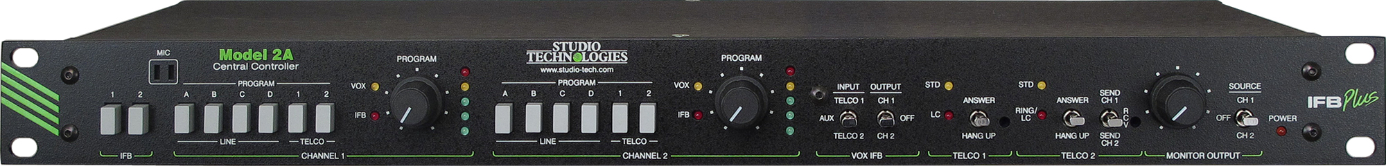
Mounted in a single space of a 19-inch rack, the Model 2A provides everything required to implement a 2-channel IFB system. Features include multiple program inputs, telephone interfaces, voice-operated (VOX) interrupt, level meters, monitor amplifier output, and an internal interrupt microphone. In addition, up to four Model 22 or Model 24 Access Stations can be connected to a Model 2A, allowing producer or director positions to access the IFB channels. In addition, up to six Model 32A or Model 33A Talent Amplifiers can be connected to a Model 2A. These portable "beltpack" units interconnect with a Model 2A using standard microphone cables. Both DC power and two channels of audio are supplied on just one 3-conductor cable, providing personnel with convenient, reliable access to the two IFB channels.
The Model 2A packs numerous features into a rugged yet lightweight single-rack-space (1U) enclosure. Standard connectors are used throughout, including 3-pin XLR, ¼-inch 2-conductor, 9-position D-subminiature, and modular telephone (RJ11) jacks. A source of 100-240 V, 50/60 hertz is connected via a detachable mains cord and provides power for the Model 2A.
IFB Channels
The Model 2A contains two independent IFB channels. Each channel has individual controls and indicators, including program source select switches, program level control, 5-segment LED level meter, and LED status indicators. The features of one of two identical channels will be highlighted in this paragraph. Six switches allow the four program audio inputs and audio coming from the two telephone interfaces to be selected as program audio sources. A rotary level control allows adjustment of the program audio level relative to that of the non-adjustable interrupt audio level. A 5-segment LED meter displays the level of the composite IFB audio signal. (The composite audio signal is the combination of the selected program audio source(s) and the interrupt audio source(s).) The level meter facilitates the rapid setting of the program level control, as well as providing a general indication of the IFB channel's signal level.
Each channel's composite IFB audio signal (a mix of program and interrupt audio) is sent to four places: a line-level output, the talent amplifier output, telephone interface 2, and the monitor output section. Each line output provides an electronically balanced, line-level signal that interfaces with external equipment via a 3-pin XLR connector. The talent amplifier output provides IFB channel 1 and 2 audio, along with 24 Vdc power on one 3-pin XLR connector. Any combination of up to six Model 32A or Model 33A units can be connected to the talent amplifier output. For application flexibility, the talent amplifier output provides 200 ohm line impedances on both of its output channels. This allows direct connection of not just listen-only devices, such as the Models 32A and 33A, but party-line (PL) user beltpacks as well. In this way popular PL beltpacks, from suppliers such RTS® and Clear-Com®, can be connected and used to create a small PL intercom system that includes IFB listen. A selector switch associated with telephone interface 2 can be used by an operator to send either IFB channel 1 or 2 out the connected phone line. The monitor output section allows loudspeaker monitoring of audio from either IFB channel 1 or 2. (An optional external loudspeaker is required.)
Program Inputs
The Model 2A contains four line-level program inputs. Each can be individually assigned to the two IFB channels, with the ability to assign multiple program inputs to an IFB channel. Program signals enter the unit via four 3-pin XLR connectors located on the unit's back panel. The program inputs are electronically balanced and feature low noise, low distortion, and high common mode signal rejection. Each program input has a trim potentiometer associated with it. The trim pots, accessible from the back panel, allow source signals with a nominal level of –10 to +8 dBu to be correctly utilized.
Program audio is muted whenever interrupt activity is taking place. Solid-state circuitry is used to provide noise-free audio switching with essentially no "clicks" or "pops" added. If desired, a program "dim" rather than a full mute can be implemented by adding two resistors to the Model 2A's circuit board.
Compressor Circuits
The two IFB channels contain studio-quality compressor circuitry to control the dynamic range of the interrupt audio. These play an important role in how the Model 2A maintains high audio quality, specifically evening out level variations presented by the talk signals associated with various IFB users. The compressors make talent cues more intelligible and prevent abnormally high signal levels from reaching user's ears. The resulting audio quality is very, very good.
Telephone Interfaces
The Model 2A contains two telephone interfaces. Both interfaces can be used to bring audio into the Model 2A from the outside world. These two audio signals can be independently assigned as program sources for IFB channels 1 and 2, as well as being used as an audio source for the voice operated (VOX) interrupt function. Each telephone interface has a receive-level trim potentiometer that is accessible via a small hole in the front panel. The large level variations that can be presented by a telephone line can make "on the fly" level trimming a useful feature. In addition to receiving audio, telephone interface 2 can be used to originate an IFB "feed" (IFB output). A switch selects if audio will be received from the outside world, or if audio from IFB channel 1 or 2 will be sent out the interface.
The telephone interfaces contain a unique feature which allows two very different types of telephone "lines" to be correctly interfaced. Each interface can be independently set to operate in either a telephone line mode or a standard audio mode. A telephone line has the profile of being a 2-wire, DC-biased (normally –48 V) circuit provided by a local telephone company, long-distance carrier, or private telephone system. A standard audio signal could be provided by, for example, a "dry" (no DC voltage provided) fax adapter associated with a cellular telephone.
When an interface is set to the telephone line mode and a telephone line with DC voltage is connected, full monitoring and control is implemented. Each interface contains a switch that allows the telephone line to be answered (taken "off hook") or hung up (placed "on hook"). DC loop current is monitored when the interface is active (off hook). If a telco-provided disconnect signal (a momentary break in loop current) is detected the interface will automatically return to its idle (on-hook) state. Telephone interface 1 contains an LED status indicator that lights whenever loop current is detected. Telephone interface 2 has a status LED that "flashes" when a ringing signal is detected and lights continuously when loop current is detected. Interface 2 also implements an auto answer function which can automatically take the telephone line to the answer (off-hook) state when a ringing signal is detected.
In many cases a "telephone line" in a mobile broadcast application is actually provided by a cellular telephone. This cellular telephone may provide a "dry" (no DC loop current) audio output signal. The standard audio mode was designed expressly to interface with this "cell phone" arrangement. In this mode, the interface's loop current-specific features are disabled, and the interface appears electrically as a transformer-coupled balanced audio interface.
When an interface has been set for the standard audio mode its front-panel line status switch is inactive as is its loop status LED. Also inactive in the standard audio mode is telephone interface 2's auto answer function. An LED associated with each telephone interface displays when the standard audio mode is selected.
Voice Operated (VOX) Interrupt
The Model 2A contains circuitry to allow an audio signal to serve as both an interrupt audio source and a control signal. This eliminates the need for a separate push-to-talk button or contact closure. The VOX feature allows an audio signal from a remote source, such as a 2-way radio or telephone line, to serve as the interrupt source. The VOX function was optimized for detecting audio signals in the voice band. As voice detection is not a trivial task, great care was taken when designing the circuitry to support this function.
Three signals can serve as the audio source for the VOX interrupt function: receive audio from telephone interface 1, receive audio from telephone interface 2, or the auxiliary audio input. The auxiliary audio input is a separate line-level audio input that is only associated with the VOX interrupt function. A 3-position switch selects which source will be used. A second 3-position switch is used to select which IFB channel is to respond to the VOX interrupt function. The VOX interrupt function can be assigned to only one IFB channel at a time or it can be disabled. Each IFB channel contains an LED indicator light to display when a VOX (voice-activated) interrupt is taking place.
Internal Interrupt Microphone
Contained behind the Model 2A's front panel is an internal interrupt microphone. Associated with the microphone are two switches, allowing the internal microphone to interrupt IFB channel 1, channel 2, or both channels 1 and 2.
Monitor Output
The Model 2A contains a simple but excellent monitor output section. At the core is a 4 watt high-performance audio amplifier designed to drive an 8 ohm (or greater) loudspeaker. (The speaker is optional and is provided as part of an installation.) Associated with the monitor output are a 3-position source select switch and a level control. The switch selects whether IFB channel 1 or IFB channel 2 will be monitored, as well as having an off position. A click-free circuit mutes the monitor output whenever the internal microphone or a Model 22 or Model 24 Access Station is interrupting either IFB channel.
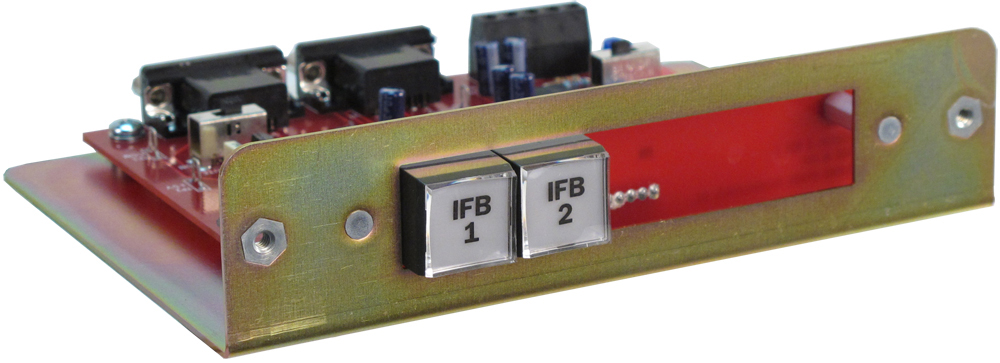
Model 22 and Model 24 Access Stations
The Model 22 Access Station and related accessories (all purchased separately) provides the capability for adding up to four additional interrupt locations. Model 22 units are intended to be installed at positions convenient to producers, directors, or other personnel who need to "cue" talent and related personnel. The unit consists of a metal chassis containing two lighted pushbutton switches, unbalanced microphone and balanced line inputs, and status and control circuitry.
The two high-quality backlit pushbutton switches provide access to the Model 2A's two IFB channels. The lights in the switches display when an interrupt is taking place on its respective channel; lighting brightly when IFB is active and dim when IFB is idle. An input select switch allows connection of a Model 11A Gooseneck Microphone or external line-level signal source. The electronically balanced line-level input allows interfacing with other communications equipment, such as "hot mic" signals from an intercom user station.
The Model 22 can be configured to mute the Model 2A's monitor amplifier output. This function will prevent acoustic feedback from occurring when a Model 22 is located close to the Model 2A's monitor speaker.
Model 22 Access Stations are linked to the associated Model 2A Central Controller via 9-pin D-subminiature female connectors. Each access station contains two connectors, allowing a simple daisy-chain installation. The nine leads carry all signals; audio, control, status lamp (tally), and power. The Model 2A provides all power required by the access stations. The Model 25A 19-Inch Rack Adapter is available to mount a Model 22 and a Model 11A Gooseneck Microphone in one space (1U) of a standard 19-inch rack. The Model 28A Panel Adapter allows a Model 22 and a Model 11A Gooseneck Microphone to be mounted in a panel opening.
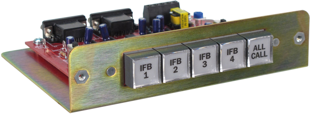
The Model 24 Access Station is similar to the Model 22 with the exception that it works with two Model 2A units. In this way production personnel can access all four of the IFB channels associated with the two Model 2A units. Up to four Model 24s can be connected to each Model 2A. A Model 24 unit consists of a metal chassis that holds five lighted pushbutton switches, audio and control circuitry, and microphone and line input connectors.
Each of the four IFB channel pushbutton switches display when an interrupt is taking place on its respective channel. A fifth button is specified as "all call" and lights when pressed. The Model 24 supports connection of an optional Model 11A Gooseneck Microphone or a line-level signal. The latter is transformer-balanced, allowing compatibility with virtually any line-level source. A switch is used to select the interrupt audio source. A second switch allows the Model 24 to mute the monitor output on each of the Model 2A units whenever an IFB channel is activated.
Model 24 Access Stations connect to the associated Model 2A units using two 9-pin D-subminiature connectors. The nine conductors that link each Model 2A with the Model 24 support all the audio, signaling, and power requirements. No external power source is required. The optional Model 27A allows a Model 24, along with a Model 11A Gooseneck Microphone, to be mounted in one space (1U) of a standard 19-inch rack enclosure.
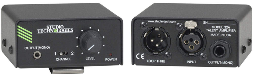
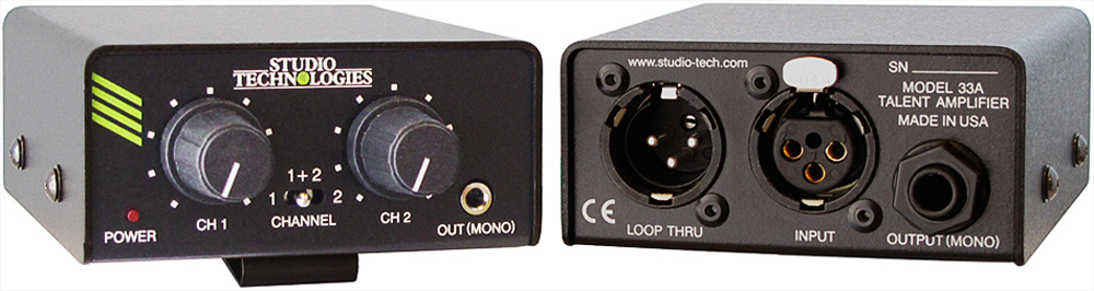
Model 32A and Model 33A Talent Amplifiers
Model 32A and Model 33A Talent Amplifiers, purchased separately, are self-contained "beltpack" units that drive talent earpieces or headsets. An audio cable with 3-pin XLR connectors on its ends links the talent amplifiers with a Model 2A. Each Model 32A and Model 33A contains both a male and female 3-pin XLR connector, allowing simple "loop through" connection of multiple units. Up to six of the talent amplifiers can be connected to, and powered by, a single Model 2A Central Controller. On each talent amplifier the audio output signal is provided on both a ¼-inch 2-conductor phone jack and a 3.5 mm output jack. An LED on each unit lights whenever power is present, providing setup assistance and user confidence. Identical in size, each is housed in a lightweight, yet rugged, aluminum housing. A belt clip allows it to be attached to belts, clipboards, scabbards, pizza boxes, production assistants, etc. An optional mounting adapter kit is available allowing a Model 32A or Model 33A to be installed in a permanent location.
The Model 32A Talent Amplifier is typically used by on-air personnel, and contains a source selection switch, along with an output level control. Either IFB channel 1 or IFB channel 2 can be sent to the talent, along with the desired audio "volume."
The Model 33A Talent Amplifier is unique in that a "mix" of IFB channels 1 and 2 can be created. Two level controls, along with a source selection switch, allows camera and production personnel to hear IFB cues from either or both channels. This allows IFB signals intended for both production personnel and on-air talent to be simultaneously monitored.